
Owner's Manual


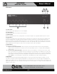
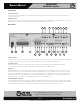
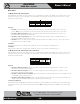
Table Of Contents
- Owners Manual
- Table of Contents
- Features
- Applications
- Parts & Controls
- Using the PHD Mixer Amplifier Diagnostic System
- How To Trouble Shoot Your Speaker System If The Limit LED Is Illuminating
- How To Trouble Shoot Your Speaker System If The Limit LED Is Illuminating
- Connecting a Remote Level Control with Remote Input Select
- Wiring the AAPHD Series Amplifier
- Level Control Security Cover Option
- Block Diagram
- Specs
- Spec Sheet
- Warranty

– 9 – AtlasSound.com
Specifications are subject to change without notice.
Owner’s Manual
AA400PHD
400W Mixer Amplifier
1601 Jack McKay Blvd. • Ennis, Texas 75119 U.S.A.
Telephone: 800.876.3333 • Fax: 800.765.3435
Rear Panel
10. Multi Function DIP Switch Inputs 2 & 3
Understanding the functionality of the DIP switches is key to maximizing the versatility of the AAPHD Series. When a switch is in the
up position, the function is “OFF or assigned to the feature stated”; when a switch is in the down position, the function is “ON or
assigned to the feature stated “.
Switch A
• DP SW #1 - Input 1 Phantom Power 24VDC is active when Input 2 or 3 is set to Mic mode and the switch is in the ON
position. Note: Only use this feature if you are using condenser microphones, otherwise leave in the “OFF” position.
• DP SW #2 - Mute Receive Inputs 2 & 3 - When “ON”, Input 2 or 3 signal will be muted if a signal is present on Input 1 or if
the Remote Mute Terminals are shorted together.
• DP SW #3 - Zone 2 Assign Inputs 2 & 3 - When “ON”, Input 2 or 3 signal will be routed to the Zone 2 Output terminals. The
signal routed is PRE the front panel level controls.
• DP SW #4 - When in the “MIC” position, Input 2 or 3 will accept microphone level signals; when in the “Line” position, Input 1
will accept line level or telephone signals.
11. Input 4
Input 4 can accept more than one type of audio signal. This input section has a 3 position Phoenix connector for Mic or Line input
signals and a 3.5mm stereo jack that is summed. The level to the amplifier mix is controlled by Input 4 level located on the front panel.
Note: Only one type of input signal can be applied at one time.
A. Balanced Mic / Line - Balanced Microphone or Line level signals connect to the (+), (–), and (G) terminals. To select between
Mic or Line input levels, refer to the DIP switch chart on the rear of the amplifier for feature assignment. If connecting an
unbalanced line level input, tie (short) the (G) and (–) terminals together for negative or ground connection and the positive or
(+) signal to the (+) terminal on the amplifier input. If the input is used in Mic mode, Phantom power for condenser type
microphones is available in the DIP switch settings on the rear panel.
B. Input 4 Stereo Summed - Input 4 consists of stereo 3.5mm summing inputs, suitable for connection to the output of iPod
®
,
CD/DVD players, etc.
12. Mic Trim
This variable control allows fine tuning of the gain of input. There is 20dB of variable gain available. The trim only applies when the
input is set to the “Mic” position on the DIP switch.
1
Phantom
Off
On
2
Mute RCV
Off
On
3
Zone 2
Off
On
4
Bal Input
Line
Mic