
Owner's Manual


AtlasIED.com – 10 –
Owner’s Manual
AA35G & AA60G
Commercial Mixer Amplifier
1601 Jack McKay Blvd. • Ennis, Texas 75119 U.S.A.
Telephone: 800.876.3333 • Fax: 800.765.3435
Choose Output Wire and Connectors
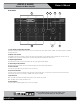
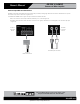
Amplifier Output Connections: Slip the cable lugs under the output screw terminals and tighten (Figure 2.5). Slide the supplied
non-touch cover over the output connections from top to bottom to cover them. AtlasIED recommends using high-quality,
two-conductor, heavy gauge speaker wire and connectors. Crimp-on spade lugs may be used for the output connectors. To prevent
the possibility of short-circuits, wrap or otherwise insulate exposed loudspeaker cable connectors. Cover the output connections with
the supplied clear non-touch cover by sliding the cover on. Using the guidelines below, select the appropriate size of wire based on the
distance from amplifier to loudspeaker. The wire sizes apply to the 81 tap.
Distance Wire Size
up to 25 ft. 16 AWG
26-40 ft. 14 AWG
41ft. + 12 AWG
NOTE: Custom wiring should only be performed by qualified personnel. Class 2 wiring is required.
CAUTION: Never use shielded cable for output power wiring.
Use 2-conductor shielded cable and a 3-pin Euroblock connector for Preamp Line Output (Figure 2.6).
Zone 2 Connections
If an external music source is connected to the AA35G or AA60G, its music can play over a phone line while the caller is on hold. Use
the connection shown in Figure 2.7 (either 81 or 6001) to connect the mixer amplifier to the Music-On-Hold input on the telephone
system interface/PBX.
Figure 2.5
Amplifier Output
Connections
Figure 2.6
Connections to the Preamp
Output Connector
Figure 2.7
Connections to the Telephone
(MOH or Amplifier Input)
Connector