
Owner's Manual


AtlasIED.com – 8 –
Owner’s Manual
AA35G & AA60G
Commercial Mixer Amplifier
1601 Jack McKay Blvd. • Ennis, Texas 75119 U.S.A.
Telephone: 800.876.3333 • Fax: 800.765.3435
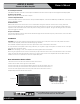
5. Line Output Connector
3-Pin Balanced Euroblock connector. Line level output is Pre Master Level control. Use this output to connect signal to a secondary amplifier.
6. Zone 2 Level Control
Potentiometer adjusts level for both Zone 2 outputs.
7. Zone 2 Output Terminals
4-terminal Euroblock connector (2 terminals for 1W output to 81 loudspeaker, 2 terminals for 6001 output to PBX MOH, music-on-hold,
port or an additional amplifier).
8. VOX Threshold
Potentiometer controls how loud the voice on CH1 must be before muting other channels. Can be set for no muting. VOX is also
known as Voice Activation Mute. This potentiometer controls the threshold of the mute bus. The mute threshold is determined by the
adjustment of this control and the level at which the person is talking into the microphone. The higher the setting the less voice level it
requires to trigger the mute bus.
9. Input 1 Connector
Five terminal Euroblock connector. Three terminals for balanced signal and two terminals for priority contact closure, which mutes other
channels when DIP switch 3 is on.
Installation
CAUTION: Ensure the mixer amplifier is disconnected from the power source, with power switch in the “Off” position and all level
controls turned completely counterclockwise before beginning installation.
Use a standard 19" (483mm) equipment rack with an optional rack-mount kit. See below for dimensions.
You may also stack mixer amplifiers without using a cabinet or you may place a single mixer amplifier on a surface with 12" of air space
around the unit for convection cooling.
NOTE: When transporting in a rack, mixer amplifiers should be supported at the front and back.
When using an equipment rack, do not mount units directly on top of each other. Allow 2 rack units (3.5") between units for convection
cooling. The side walls of the rack should be a minimum of 2" (51mm) away from the mixer amplifier sides and the back of the rack
should be a minimum of 4" (102mm) from the mixer amplifier back panel.
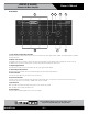
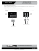
How to Attach the Unit to a Rack
1. Remove the two screws from each side of the chassis near the front.
2. Place a rack ear flush with the right front of the chassis.
3. Insert a screw that you removed into the bottom hole of the rack ear and chassis. Screw it in.
4. Insert a screw that you removed into the center hole of the rack ear and chassis. Screw it in.
5. Insert one of the supplied screws into the top hole of the rack ear and chassis. Screw it in.
6. Repeat steps 3-6 for the left side of the chassis.
Figure 2.2
How to Connect Rack Ears
9.5" (241mm)
3.5" (89mm)