
Owner's Manual


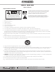
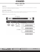
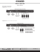
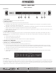
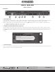
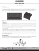
Table Of Contents
- Owner’s Manual
- Table of Contents
- Important Safety Instructions
- WARNINGS
- Introduction
- Key Features
- Applications
- AZA Amplifier Configurations
- Front Panel
- Rear Panel
- Rack Ear Installation
- Finding an AZA Amplifier On a LAN
- AZA Amplifier Discovery Software
- Logging into The Amplifier The First Time
- Changing Login Username & Password For The First Time
- Resetting the Password
- AZA UI Overview
- AZA Factory Default UI Settings
- Firmware Revision
- Static IP Addresses
- Resetting the Amp to DHCP Mode
- Resetting the Login Username & Password
- Changing the Amplifier (Host) Name
- Accessory Card Installation
- Installation and Considerations
- Dimensional Drawings
- Warranty

– 10 –
AZA Series
Owner’s Manual
AtlasIED.com
TELEPHONE: (800) 876-3333
SUPPORT@ATLASIED.COM
1601 JACK MCKAY BLVD.
ENNIS, TEXAS 75119 U.S.A.
Rear Panel
4. Speaker Connection
A screw terminal block connector is supplied to connect speakers to the AZA amplifier. It is recommended to use Class 3 rated, 14-gauge wire or
lower for speaker wiring. Amplifier output channel configurations are in the amplifier web UI. The AZA is shipped with two speaker output terminal
covers. AtlasIED recommends placing the security covers on the amplifier after wiring and before turning the amplifier on for configuration. Included in
the carton are eight (8) Yellow Spade Lug 0.250 OD spade crimp terminals that accept up to 12-gauge wire and four (4) security cover screws
(M3 x 8mm). Terminal block screws are M4.
Note: The AZA amp is preconfigured at the factory for four-channel 70V/100V mode. Follow the manual wiring information to connect the distributed
audio system.
5. Ethernet Port
Connect the amplifier to a network, local computer, or router / switch using CAT5 (or greater) cable to access the amplifier’s DSP and control settings.
6. Control Ports
The AZA Series allows you to assign / configure the four control ports located on the rear of the amplifier to perform Remote Level or Mute functions.
Note: Each Control Port pin can only be assigned to one function such as Mute or Level, but not both. Control Port assignment is done in the AZA UI
Advance Setting section. Note: If you are using the amplifier with an Atmosphere Zone Master, these features are not needed. Refer to the AZA404 &
AZA804 Advance Settings Manual located at https://www.atlasied.com/Atmosphere/AZA/
7. Accessory Card Slot
An additional four (4) inputs can be routed to any of the four (4) output channels using an optional accessory card, AtlasIED model DPA-DAC4, which
includes four (4) channels of Dante™ digital audio. Contact AtlasIED for a list of additional accessory cards. See section “Accessory Card Installation”
on page 17 for information on installation or damage may occur. Note: Accessory card installation must be done by a qualified technician. Note: In
standby mode there are DC voltages present at the accessory card port. The AZA amplifier must be removed from the AC Mains source in order to
prevent damage to the card or amplifier. Accessory card initialization is done through the Advance Settings Button in the AZA UI. Note: If you are using
the amplifier with an Atmosphere Zone Master, these features are not needed. Refer to the AZA404 & AZA804 Advance Settings Manual located at
https://www.atlasied.com/Atmosphere/AZA/
Rack Ear Installation
The AZA amplifiers come with removable rack ears for mounting the amplifier into a 19" equipment rack. Included are two (2) universal Left and Right
rack ears. Each rack ear requires four (4) M4 x 8MM Pan Head Phillips screws. Nine (9) of these screws are included in the box.