
Owner's Manual


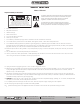
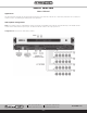
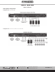
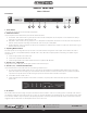
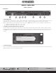
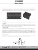
Table Of Contents
- Owner’s Manual
- Table of Contents
- Important Safety Instructions
- WARNINGS
- Introduction
- Key Features
- Applications
- AZA Amplifier Configurations
- Front Panel
- Rear Panel
- Rack Ear Installation
- Finding an AZA Amplifier On a LAN
- AZA Amplifier Discovery Software
- Logging into The Amplifier The First Time
- Changing Login Username & Password For The First Time
- Resetting the Password
- AZA UI Overview
- AZA Factory Default UI Settings
- Firmware Revision
- Static IP Addresses
- Resetting the Amp to DHCP Mode
- Resetting the Login Username & Password
- Changing the Amplifier (Host) Name
- Accessory Card Installation
- Installation and Considerations
- Dimensional Drawings
- Warranty

– 8 –
AZA Series
Owner’s Manual
AtlasIED.com
TELEPHONE: (800) 876-3333
SUPPORT@ATLASIED.COM
1601 JACK MCKAY BLVD.
ENNIS, TEXAS 75119 U.S.A.
Front Panel
1. Power Switch
This toggles the amplifier between Active Mode or Sleep Mode.
2. LED Power Indicator
The AZA amplifier has three states of idle power that are indicated as follows:
A. Active Mode - When the LED outer ring of the power switch illuminates a steady blue color, the amplifier is in Active Mode and is ready to
pass audio. This is AZA factory default shipping mode.
B. Sleep Mode - When the LED outer ring is Off, the unit is in Sleep Mode. In Sleep Mode, the Ethernet is active for access to the amplifiers on
board UI while the amplifier output stage and DSP are Off. Audio will not pass in Sleep Mode.
C. Standby APD Mode - When the amplifier Auto Power Down (APD) feature is enabled and the amplifier is in APD mode, the LED outer ring will
blink blue once every 5 seconds.
3. Operating Mode Indicators
Each AZA amplifier can be configured three ways. The LEDs in this area indicate the configuration of the amplifier. These indicators illuminate if
Channels 1 / 2 and 3 / 4 are operated separately in 4Ω / 8Ω mode or 70V / 100V mode. Amplifier operation mode setting is completed using the
internal DSP UI.
A. 4-Channel high impedance 70V / 100V mode
B. 4-Channel low impedance 4Ω or 8Ω mode
C. 2-Channel high impedance 70V / 100V mode & 2-Channel low impedance 4Ω / 8Ω mode
4. Channel 1, 2, 3, 4 Signal LED
The Signal LED will illuminate green if audio signal is present at that channel’s output.
5. Channel 1, 2, 3, 4 Limit/Protect/Mute LED
The Limit/ Protect LEDs will illuminate red if one of the following conditions occurs:
A. Any channel of the AZA amplifier reaches maximum output power. The AZA features an adjustable amplifier OUTPUT limiter which helps
prevent the amplifier from hard clipping. An occasional flash of the LED is OK but if the LED illuminates continuously reduce the amplifier’s
input level. If the Clip LED remains On after reducing the input level, recheck the load connected to the amplifier.
B. The OUTPUT has been muted in the UI.
C. A fault is detected within the amplifier. Once the fault is corrected, it may be required to reset the AC Mains power to reset the amplifier
protect mode.
6. Air Exhaust
Each model includes convection cooling with dynamic fan assist for extreme conditions. If the unit is not being used or is in Standby mode, the fan is
not needed for cooling and remains Off until the unit is in heavy use. As heat is generated in the amplifier during use, the fan activates at a low speed
and increases as needed to keep the amplifier at safe operating temperature. This cooling method eliminates the need for air filters that can become
clogged and require maintenance. The AZA amplifier’s air flow is from rear to front.
4 5 3 66 12