
Owner's Manual
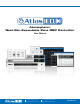

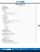

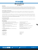
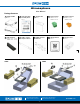


Table Of Contents
- User Manual
- Table of Contents
- Important Safety Instructions
- Introduction
- Key Features and Applications
- Package Contents
- Rack Installation Guide
- Hardware Overview
- Connections
- Network Connection Overview
- Software Overview
- Sources
- Zones (Zone Outputs)
- Zones-Limiter
- Zones-Groups Overview
- Room Combine Active
- Message Player Overview
- Messages
- GPIO Overview
- Scenes Overview
- Routines Overview
- Accessories Overview
- Accessories Page
- Print, Assemble, Place, and Scan
- X-ANS General Settings
- Accessories Connection Rules
- Scheduler, Steps to Create an Event
- Diagrams – Connection Diagram and Block Diagram
- Settings Page Overview
- Front Panel Display Menu Tree
- Specifications
- Mechanical Line Drawings with Dimensions
- Regulatory Information: AZM4 / AZM8 / A-BT
- Limited Warranty, Customer Service Online Warranty Claim Process
- Quick Start Guide
- Product Info
- System Examples

Atmosphere
User Manual
AtlasIED.com
TELEPHONE: (800) 876-3333
SUPPORT@ATLASIED.COM
1601 JACK MCKAY BLVD.
ENNIS, TEXAS 75119 U.S.A.
– 8 –
Rack Installation Guide
To rack mount the AZM8, remove included rack ears and fasteners from hardware box and attach to each side.
To rack mount the AZM4, remove included rack ear and ½ rack adapter and fasteners from hardware box and attach to each side.
Note: The AZM4 is a ½-RU device and can be mounted in a side-by-side configuration using the AtlasIED part # PA702-RMK rack kit. It can also be
combined with the IP power strip AtlasIED AP-S15HRIP.
Note: When rack mounting the AZM, the fan air flow is from front to back.