
Warranty Manual


AT-GAIN-120
10
PWR
VOL LEVEL
AUDIO AMPLIFIER
FWSIGNAL ANALOG IN
NET AUDIODEVICE ID
GAIN
TM
LAN
RESET RESET
LINE OUT
CLASS 2 WIRING CLASS 2 WIRING
TRIGGER MODE
MODEL:
dB
-22
-2
-4
-20
-19
-14
-9
-22
-2
-4
-20
-19
-14
-9
dB
ANALOG IN
L
4 / 8 Ω OUT 70V / 100V OUT
AT-GAIN-120
PWR: 100-120VAC 60Hz 120W
220-240VAC 50Hz 120W
L R L R
IP
4Ω
8Ω 100V
70V
R
INPUT GAIN
L R
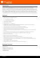
Panel Description
1
4
6 8 11 13 15
5 107 9 1412
2 3
Front
Rear
1 LED indicators
Displays the current state of the unit. Refer to LED
Indicators (page 19) for more information.
2 VOL LEVEL
Displays the output audio level.
3 FW
Connect a USB-to-mini USB cable to this port from a
computer for rmware updates.
4 LAN
Connect an Ethernet cable from this port to the Local
Area Network (LAN).
5 Removable Faceplate
Remove this faceplate to install the AT-GAIN-NET
(not included) card. Refer to Network Audio Card
Installation (page 40) for more information.
6 ANALOG IN
Connect an audio source to this port using the
included 5-pin captive screw connector. Refer to
Audio Connectors (page 11) for wiring information.
7 RESET
Press and hold this button for 10 seconds to reset
the unit to factory-default settings. Refer to Factory
Reset (page 27) for more information.
8 LINE OUT
Use the included 5-pin captive screw connector
to connect to another AT-GAIN-120, audio DSP, or
audio mixer. Refer to Audio Connectors (page 11)
for more information.
9 IP RESET
Press and hold button this button for 10 seconds to
switch between DHCP and static IP mode. Refer to
IP Conguration (page 15) for more information.
Also press and hold for 3 seconds to bring the unit
out of hibernation mode. Refer to Power Modes
(page 20) for more information.
10 TRIGGER
Use this port to toggle the unit between on and
standby or awaken the unit from hibernation mode.
11 4 / 8 Ω OUT
Connect a pair of 4 or 8 ohm speakers (low-
impedance) to this port using the included 4-pin
captive screw connector.
12 INPUT GAIN
Use a regular screwdriver to adjust the input gain
level for left and right channel.
13 70V / 100V OUT
Connect a distributed speaker system (high-
impedance) to this port using the included 2-pin
captive screw connector.
14 MODE
Slide the switch to select between 4Ω, 8Ω, 70V, or
100V modes.
15 PWR
Connect from a power source to the AT-GAIN-120
using the included IEC power cord.