
Installation Guide


4
Installation Guide
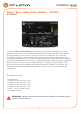
AT-GAIN-60
Installation
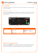
1. Connect an analog audio source to the AUDIO IN ports. Once connected, press the INPUT
button on the front panel, to switch between the RCA and the 5-pin captive screw port.
• RCA cables (unbalanced)
Connect shielded RCA-type cables from the audio source to the AUDIO IN 2 left/right
RCA jacks.
• Balanced/Unbalanced
Connect the included 5-pin captive screw to the AUDIO IN 1 port. Use the desired
wiring conguration, on the previous page.
2. Determine the use-case scenario of the AT-GAIN-60. The AT-GAIN-60 can be congured as
either one of the following. Only one type of speaker connection is permitted at a time.
• Distributed speaker system (high impedance)
Set the OUTPUT MODE switch to the required voltage setting: 24V, 70V, or 100V.
This mode is used for commercial applications and longer speaker cable runs.
• Program speakers / stereo (low impedance)
Set the OUTPUT MODE switch to the impedance setting of the speakers being
connected: 4Ω or 8Ω. This mode is used for consumer applications and shorter
speaker cable runs.
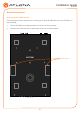
Refer to Connection Diagrams (page 7) for example applications.
3. Connect the speakers to the proper port on the AT-GAIN-60, based on the selection made
in the previous step.
4. Connect the LAN port to a network switch for set up and control of the unit.
5. Connect the included power supply to the DC 28V power receptacle.
6. Connect the IEC power cable to an available electrical outlet.
NOTE: The AT-GAIN-60 only supports one type of speaker connection at a time:
high-impedance or low-impedance.
DC28VAUDIO IN 2
INPUT GAIN
L R
L
TX RX
R
3.4A
-22
-2
-4
-20
-19
-14
-9
CLASS 2 WIRING
24 / 70 / 100V OUT
CLASS 2 WIRING
dB
Distributed speakers (high-Z)
Program / stereo speakers (low-Z)