
Instructions/Assembly Guide

2
Installation Guide
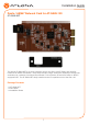
AT-GAIN-NET
Network Card Installation
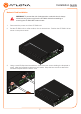
1. Disconnect the power cord from AT-GAIN-120.
2. Set the AT-GAIN-120 on a at surface, free of obstructions. Position the AT-GAIN-120 as
shown in the picture below.
3. Using a small Phillips-head screwdriver, remove the two screws holding the faceplate in
place. After the faceplate is removed, set it aside. Keep the two screws to attach the
included faceplate with the INPUT card.
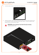
WARNING: To prevent the risk of electrocution or electric shock, always
disconnect the power cord from the AT-GAIN-120 before installing or
removing the AT-GAIN-NET network card.
LAN
RESET RESET
LINE OUT
CLASS 2 WIRING CLASS 2 WIRING
TRIGGER MODE
MODEL:
dB
-22
-2
-4
-20
-19
-14
-9
-22
-2
-4
-20
-19
-14
-9
dB
ANALOG IN
L
4 / 8 Ω OUT 70V / 100V OUT
AT-GAIN-120
PWR: 100-120VAC 60Hz 120W
220-240VAC 50Hz 120W
L R
IP
4Ω
8Ω 100V
70V
R
INPUT GAIN
L R
L R
LAN
RESET RESET
LINE OUT
CLASS 2 WIRING CLASS 2 WIRING
TRIGGER MODE
MODEL:
dB
-22
-2
-4
-20
-19
-14
-9
-22
-2
-4
-20
-19
-14
-9
dB
ANALOG IN
L
4 / 8 Ω OUT 70V / 100V OUT
AT-GAIN-120
PWR: 100-120VAC 60Hz 120W
220-240VAC 50Hz 120W
L R
IP
4Ω
8Ω 100V
70V
R
INPUT GAIN
LAN
RESET RESET
LINE OUT
CLASS 2
TRIGGER
ANALOG IN
L
4 / 8 Ω
L R
IP
R