
Instructions/Assembly Guide

3
Installation Guide
AT-GAIN-NET
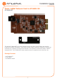
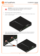
4. Locate the plastic guides on either side of the expansion slot.
5. Carefully position the card between the upper and lower rail of each guide, and gently push
the AT-GAIN-NET network card forward, until it locks in place. The card will make a small
snapping sound, once the card is in place.
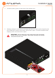
IMPORTANT: When handling the card, avoid touching the components.
Always hold the card by the edges. Electrostatic discharge can damage
components and the card.
L R
LAN
RESET RESET
LINE OUT
CLASS 2 WIRING CLASS 2 WIRING
TRIGGER MODE
MODEL:
dB
-22
-2
-4
-20
-19
-14
-9
-22
-2
-4
-20
-19
-14
-9
dB
ANALOG IN
L
4 / 8 Ω OUT 70V / 100V OUT
AT-GAIN-120
PWR: 100-120VAC 60Hz 120W
220-240VAC 50Hz 120W
L R
IP
4Ω
8Ω 100V
70V
R
INPUT GAIN
L R
LAN
RESET RESET
LINE OUT
CLASS 2 WIRING CLASS 2 WIRING
TRIGGER MODE
MODEL:
dB
-22
-2
-4
-20
-19
-14
-9
-22
-2
-4
-20
-19
-14
-9
dB
ANALOG IN
L
4 / 8 Ω OUT 70V / 100V OUT
AT-GAIN-120
PWR: 100-120VAC 60Hz 120W
220-240VAC 50Hz 120W
L R
IP
4Ω
8Ω 100V
70V
R
INPUT GAIN