4K / UHD Two-Input Wallplate Switcher for HDMI with Ethernet-Enabled HDBaseT™ Output AT-HDVS-210H-TX-WP Atlona Manuals Switchers
Version Information Version Release Date Notes 1 Nov 2017 Initial Release 2 Feb 2018 f/w 1.0.11; added InputStatus and InputBroadcast commands 3 Mar 2018 Commands moved to separate API document 4 Jun 2019 1.0.
Welcome to Atlona! Thank you for purchasing this Atlona product. We hope you enjoy it and will take an extra few moments to register your new purchase. Registration only takes a few minutes and protects this product against theft or loss. In addition, you will receive notifications of product updates and firmware. Atlona product registration is voluntary and failure to register will not affect the product warranty. To register your product, go to http://www.atlona.
Atlona, Inc. (“Atlona”) Limited Product Warranty Coverage Atlona warrants its products will substantially perform to their published specifications and will be free from defects in materials and workmanship under normal use, conditions and service.
Atlona, Inc. (“Atlona”) Limited Product Warranty • Damage, deterioration or malfunction resulting from the installation or removal of this product from any installation, any unauthorized tampering with this product, any repairs attempted by anyone unauthorized by Atlona to make such repairs, or any other cause which does not relate directly to a defect in materials and/or workmanship of this product.
Important Safety Information CAUTION RISK OF ELECTRIC SHOCK DO NOT OPEN CAUTION: TO REDUCT THE RISK OF ELECTRIC SHOCK DO NOT OPEN ENCLOSURE OR EXPOSE TO RAIN OR MOISTURE. NO USER-SERVICEABLE PARTS INSIDE REFER SERVICING TO QUALIFIED SERVICE PERSONNEL. The exclamation point within an equilateral triangle is intended to alert the user to the presence of important operating and maintenance instructions in the literature accompanying the product.
Table of Contents Introduction 8 Features 8 Package Contents 8 Panel Description 9 Installation RS-232 Connector Connection Instructions Connection Diagram Faceplate Removal and Assembly IP Configuration Setting the IP Mode Setting the IP Address Using Commands Setting the IP Address using the Web GUI Resetting to Factory-Default Settings 10 10 11 12 13 14 14 15 15 16 The Web GUI Introduction to the Web Server Menu Bar Toggles Buttons Info page A/V Settings page Display page RS-232 page EDID page
Introduction The Atlona AT-HDVS-210H-TX-WP is a 2×1 switcher and HDBaseT transmitter with two HDMI inputs. It features a US one-gang, Decora-style wallplate form factor, and includes interchangeable black and white wallplates and faceplates. Video signals up to 4K/UHD @ 60 Hz with 4:2:0 chroma subsampling, plus embedded audio and control can be transmitted up to 330 feet (100 meters). The HDVS-210H-TX-WP is HDCP 2.2 compliant.
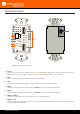
HDMI 1 Panel Description PWR 3 LINK 4 HDMI 1 5 HDMI 2 HDBaseT OUT 6 HDMI 2 2 RS-232 RX TX 1 7 Front Rear Wallplate with white trim is shown 1 RS-232 Remove this cover to expose the RS-232 port. Connect an RS-232 cable, with a 3-pin captive screw connector, from this port to a control system. Refer to RS-232 Connector (page 10) for more information. 2 PWR This LED indicator glows solid green when the unit is powered.
Installation RS-232 Connector The AT-HDVS-210H-TX-WP provides RS-232 control between an automation system and an RS-232 device. This step is optional. 1. Remove the small plate covering the RS-232 port on the faceplate. PW K LIN HD K HDMI 2 1 MI 1 MI HD 2 MI MI HD HD HDMI1 HDMI 2 R R PW LIN RS-232 RX TX RX TX AT P -W -TX 10H 2 VS- -HD HDMI1 -HD AT small plate RS-232 VS P -W -TX 0H -21 2 2. Use wire strippers to remove a portion of the cable jacket. 3.
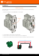
Installation Connection Instructions 1. Determine the proper faceplate to be used for installation. If using the black faceplate, then refer to Faceplate Removal and Assembly (page 13) for information on changing the faceplate. 2. Connect an Ethernet cable, from the HDBaseT OUT port, on the rear of the unit, to one of the following devices. Ethernet cables should use EIA/TIA-568B termination: a. PoE-compatible receiver (not included), such as the AT-HDVS-200-RX. Refer to Figure 1 on the next page. b.
Installation Connection Diagram Figure 1 1-gang electrical box or mud ring Wall cross-section C1 2 DC COM 19V C2 T MI OU HD FW 1 ET ERN eT ETH Bas HD I OUT LAN HDM MD P OUT DC 48V IN HD Ba AT-HDVS-200-RX AT-VGW-250 seT t rne e Eth White Decora®-style wallplate (included) t rne P -W TX 10H- S-2 -HDV RS-232 AT RX TX e Eth HDMI 1 -250 GW AT-V R K LIN MI 1 MI 2 HDMI 2 PW HD HD Vid eo AV LAN AT-HDVS-210H-TX-WP Eth e rne t/ Po E Laptop Vid eo AT-
Installation Faceplate Removal and Assembly The AT-HDVS-210H-TX-WP includes an optional black faceplate and wallplate. Removal of the faceplate requires that the AT-HDVS-210H-TX-WP be disassembled from the electrical box or mud ring. 1. Remove the wall plate from the electrical box and slide out the AT-HDVS-210H-TX-WP assembly, as shown. It is recommended that the Ethernet cable, connected to the HDBaseT OUT port, be disconnected from the unit, to allow for easy installation of the faceplate.
Installation IP Configuration The AT-HDVS-210H-TX-WP is shipped with DHCP enabled. Once connected to a network, the DHCP server (if available), will automatically assign an IP address to the unit. Use an IP scanner, along with the MAC address on the back of the unit, to identify both the unit and its IP address on the network. If a static IP address is desired, the unit can be switched to static IP mode. Use one of the following procedures to switch between DHCP and static IP mode.
Installation Setting the IP Address Using Commands Use the IPStatic and IPDHCP commands to switch between DHCP and IP mode through RS-232 or Telnet. Refer to API documentation for more information. All commands and their arguments are case-sensitive. • Setting static IP mode 1. Connect to the AT-HDVS-210H-TX-WP using RS-232 or Telnet. 2. At the command line, execute the IPDHCP command using the off argument, as shown. IPDHCP off 3. Execute the IPStatic command.
Installation Resetting to Factory-Default Settings Resetting the AT-HDVS-210H-TX-WP requires that the front faceplate be removed. Refer to Faceplate Removal and Assembly (page 13) for more information. 1. Remove the faceplate from the AT-HDVS-210H-TXWP. 2. Press and hold the Reset button for 15 seconds. 3. Release the Reset button. During the reboot process, the PWR LED indicator will glow red. The unit will be operational when the PWR LED indicator glows blue. PWR LED indicator 4.
The Web GUI Introduction to Web GUI The AT-HDVS-210H-TX-WP includes a built-in web GUI. Atlona recommends that the web GUI be used to set up the AT-HDVS-210H-TX-WP, as it provides intuitive management of all features. The AT-HDVS-210H-TX-WP is shipped with DHCP enabled. Once connected to a network, the DHCP server will automatically assign an IP address to the unit. Use an IP scanner to determine the IP address of the AT-HDVS-210HTX-WP. If a static IP address is desired, refer to IP Configuration (page 14).
The Web GUI 4. Type root, using lower-case characters, in the Username field. 5. Type Atlona in the Password field. This is the default password. The password field is case-sensitive. When the password is entered, it will be masked. The password can be changed, if desired. Refer to the Config page (page 29) for more information. 6. Click the Submit button or press the ENTER key on the keyboard. 7. The Info page will be displayed. 8.
The Web GUI Menu Bar The dark-colored bar, near the top of the screen, is the menu bar. When the mouse is moved over each menu element, it will be highlighted in light orange. Once the desired menu element is highlighted, click the left mouse button to access the settings within the menu. Menu bar In this example, clicking A/V Settings, in the menu bar, will display the A/V Settings page. Toggles Several settings within the Web GUI use toggles, which enable, disable, or assign one of two settings.
The Web GUI Buttons Buttons are used to execute an action or setting. Several pages within the Web GUI include a Save button. Clicking the Save button will apply and save all settings in the current page.
The Web GUI Info page Model Name The model SKU of this product. Software Version The version of firmware that the AT-HDVS-210H-TX-WP is running. Always make sure to check the AT-HDVS-210HTX-WP product page, on the Atlona web site, for the latest version of firmware. On-Time (h-m) The time elapsed since the unit was last powered-on. Turning the unit “off”, using the PWOFF command, will not reset this field. RX Type Displays the model of the receiver unit (if connected).
The Web GUI A/V Settings page Input Selection Click the drop-down list to select the desired input. Setting Description Input 1 HDMI 1 Input 2 HDMI 2 Auto Switch Three controls are available under the Auto Switch feature. • Auto Switch Click this toggle switch to enable or disable auto-switching. When enabled, the AT-HDVS-210H-TX will automatically switch to the another port, if the signal is disrupted on the currently active input.
The Web GUI HDCP Settings Sets the HDCP reporting mode of the specified HDMI port. Input 1 = HDMI 1; Input 2 = HDMI 2. Some devices, such as Mac computers will transmit HDCP content if an HDCP-compliant display/sink is detected. Setting this value to OFF, will instruct the source to send non-HDCP content (if possible) to non-HDCP display and/or sink devices. Note that setting this value to OFF will not decrypt HDCP content.
The Web GUI Display page CEC Command Click the ON or OFF button to turn the display on or off using CEC. Consumer Electronics Control (CEC): Atlona has confirmed proper CEC functionality with several current models of Samsung, Panasonic, and Sony displays. However, it is not guaranteed that CEC will work with all displays. Many manufacturers do not support the CEC “off” command, and older displays use proprietary commands. Atlona only supports displays that use the CEC command structure defined in HDMI 1.
The Web GUI Auto power off timer Sets the time interval, in seconds, between when the loss of A/V signal is detected and when the “Display Off” command is sent. Range: 5 seconds to 1 hour. Power on delay timer (Sec.) Sets the time interval, in seconds, between when the system is powered-on, and when system can re-enter the Auto Power Off state. All display-on commands are triggered immediately after an A/V source is connected. Range: 0 to 300. Control Type Sets the control method for sending commands.
The Web GUI IP Address Enter the IP address of the device in this field. Port Enter the listening port of the device in this field. Username Enter the username for login. If the IP Mode is set to Non-Login, then this information will not be required. Password Enter the password for login. If the IP Mode is set to Non-Login, then this information will not be required. Save Click this button to save all changes in this window group. Send Mode Sets the display format for the commands in the web GUI.
The Web GUI RS-232 page Zone When the AT-HDVS-210H-TX-WP is connected to the AT-HDVS-200-RX, the drop-down list boxes will be disabled and the HDBaseT baud rate will be locked at 115200. If the AT-HDVS-210H-TX-WP is connected to another HDBaseT device, such as the AT-UHD-CLSO-824, each of these drop-down list boxes can be set to the baud rate of the HDBaseT RS-232 settings on the corresponding device. Click the Save button to accept the settings.
The Web GUI EDID page EDID Settings Click these drop-down lists to select the desired EDID to be used for each input. Input 1 = HDMI 1, Input 2 = HDMI 2. The source device will use the information in the EDID, before sending A/V data to the sink device.
The Web GUI Config page Old Username This field cannot be changed. “root” is the administrator user. Old Password Enter the current password for the “root” username in this field. The default password is “Atlona”. New Username This field cannot be changed. Save Click this button to save all changes. New Password Enter the new password fro the “root” username in this field. Confirm New Password Verify the new password by retyping it in this field. All User Login Settings • Username Displays the username.
The Web GUI System page IP Mode Click this toggle to set the IP mode of the AT-HDVS-210H-TX-WP. The default setting is DHCP. Available settings: STATIC IP, DHCP. IP Enter the IP address of the AT-HDVS-210H-TX-WP in this field. This field will only be available if IP Mode is set to STATIC IP. The default IP address is 192.168.1.254. Netmask Enter the subnet mask in this field. This field will only be available if IP Mode is set to STATIC IP. Gateway Enter the gateway (router) address in this field.
The Web GUI Power Under normal operation conditions, this toggle is set to ON. Click this toggle to OFF, to turn the AT-HDVS-210H-TXWP “off”. When “off”, the PWR LED indicator will turn red. The PWOFF and PWON commands can also be used to control the power state. Reset to Default Click the Factory Default button to set the AT-HDVS-210H-TX-WP to factory-default settings. Firmware Update Click the Choose File button to select the firmware file, when upgrading the firmware on the AT-HDVS-210H-TX-WP.
The Web GUI HDBT page HDBaseT Zone The AT-HDVS-210H-TX-WP has only a single HDBaseT output. Therefore, this drop-down list is disabled. Start Click the Start button to being the HDBaseT testing. During testing, the button text will change to “Stop”. Click the Stop button to halt the HDBaseT testing process. TX Version The version of the Valens chip on the transmitter. RX Version The version of the Valens chip on the receiver. TMDS Clock Displays the pixel clock speed.
Appendix Updating the Firmware Updating the firmware can be completed using either the USB interface or the web GUI. Atlona recommends using the web GUI for updating the firmware. However, if a network connection is not available, the AT-HDVS-210HTX-WP firmware can be updated using a USB-A to USB mini-B cable. Using the Web GUI Requirements: • • • AT-HDVS-210H-TX-WP Firmware file Computer 1.
Appendix 6. The following message box will be displayed. 7. Click the OK button to begin the firmware update process. Click the Cancel button to cancel the process. 8. After the firmware update process is complete, the Login screen will be displayed. Using USB Requirements: • • • • AT-HDVS-210H-TX-WP Firmware file Computer running Windows USB-A to USB mini-B cable 1. Disconnect power from the AT-HDVS-210H-TX-WP, by disconnecting the Ethernet cable from the HDBaseT OUT port on the unit. 2.
Appendix 4. Connect the USB-A to USB mini-B cable between the PC and the firmware port on the AT-HDVS-210H-TX-WP. The unit will be powered by the USB cable. 5. The USB UPDATE folder will be displayed. If this folder is not displayed, automatically, select the USB UPDATE drive from Windows Explorer. 7. Delete all files from the USB UPDATE drive, if any are present. 8. Drag-and-drop the firmware file to the drive. 9.
Appendix Default Settings The following tables list the factory-default settings for the AT-HDVS-210H-TX-WP.
Appendix Specifications Video UHD/HD/SD 4096×2160@24/25/30/50*/60Hz*, 3840×2160@24/25/30/50*/60Hz*, 2048x1080p, 1080p@23.98/24/25/29.97/30/50/59.94/60Hz, 1080i@50/59.94/60Hz, 720p@50/59.
Index A P Audio muting 23 Panel descriptions 9 Password default 17 PoE compatible receiver 11 power injector 11 C CEC compatibility 24 Configuration IP.
Toll free US International atlona.com • 877.536.3976 • 41.43.508.4321 © 2019 Atlona Inc. All rights reserved. “Atlona” and the Atlona logo are registered trademarks of Atlona Inc. All other brand names and trademarks or registered trademarks are the property of their respective owners. Pricing, specifications and availability subject to change without notice. Actual products, product images, and online product images may vary from images shown here.