
User Manual

AT-OME-ST31
23
Advanced Operation
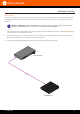
1. Identify the DE-9 connector that will be attached to the control system or computer (DCE) equipment.
2. Remove the DE-9 connector at the opposite end of the cable with wire cutters.
3. Remove at least 1” of the cable insulation to expose each of the nine wires.
4. Locate a multimeter and set it to the “continuity” function.
5. Attach one of the leads from the multimeter to pin 2 on the DE-9 connector.
6. Take the other lead and probe each of the wires on the opposite end of the cable. When the wire connected to
that pin is detected, the multimeter will emit an audible tone. Once this occurs, identify the current wire, and
move it to the side.
7. Repeat step 6 for pin 3 and pin 5 on the DE-9 connector.
8. Group the remaining wires and pull them aside. Electrical tape can be use to secure the wires to the outside of
the RS-232 cable.
9. Remove at least 3/16” (5 mm) of insulation from the TxD, RxD, and GND wires.
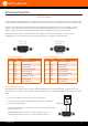
Cable Assembly
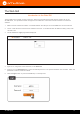
When connecting a DTE device to a DCE device, a straight-through cable should be used. A straight-through cable
is wired in such a way that the pins on one side of the cable are connected to the corresponding pins on the opposite
side of the cable, as shown in the table below. However, the AT-OME-ST31 will use only TxD, RxD, and GND signals
when communicating with a control system or computer.
Pin Signal Signal Pin
1 DCD DCD 1
2 RxD TxD 2
3 TxD RxD 3
4 DTR DSR 4
5 GND GND 5
6 DSR DTR 6
7 RTS CTS 7
8 CTS RTS 8
9 RI RI 9
Straight-Through Cable
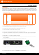
GND
RxD
TxD
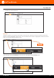
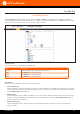
10. Locate the included 3-pin captive screw block and open each of the terminals by
turning the screws counter-clockwise, using a small regular screwdriver.
11. Insert the TxD, RxD, and GND wires into correct terminal, as shown, and tighten the
screws to secure each wire. Do no overtighten.
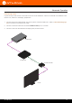
12. Connect the captive screw connector to the RS-232 port on the AT-OME-ST31.
OMEGA
TM
PWR
LINK
FW
1
2
3
INPUT DISPLAY
AT-OME-ST31
AUDIO
INPUT
1 2 3
AT-OME-ST31
OUTPUT RESET
IP MODE
RX TX
RS-232 LAN DC 24V