
Installation Guide


Installation Guide
2
AT-RON-448
OUTPUT
1 2 3 4
DC 5V
BACKUP
DC 5V
MAINANALOG S/PDIF
HDMI IN
AT-RON-448
FW
-
-
L R
+
+
5 6 7 8
AT-RON-448 EDID
INT LEARN
1
2
3 4 5 6
7 8
SYNC
POWER
BM
OUTPUT
1 2 3 4
DC 5V
BACKUP
DC 5V
MAINANALOG S/PDIF
HDMI IN
AT-RON-448
FW
-
-
L R
+
+
5 6 7 8
AT-RON-448 EDID
INT LEARN
1 2 3 4 5 6 7 8
SYNCPOWER
BM
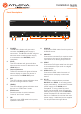
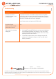
1 POWER
This M LED indicator will glow solid
red when the MAIN power supply is
connected. The B LED indicator will glow
solid red when a backup power supply
is connected to the BACKUP power
receptacle.
2 SYNC
This LED indicator will glow solid blue
when an active source is detected on the
HDMI IN port.
3 Output Indicators
These LED indicator will glow solid blue
when a display or other sink device is
connected to the HDMI OUT ports.
4 INT
This LED indicator glows solid blue when
the unit is using the built-in EDID.
5 LEARN
This LED indicator glows solid blue when
the unit is in “EDID learn” mode.
6 EDID button
Press this button to switch between
“internal” and “learn” modes.
7 FW
Connect a mini USB cable to this port to
update the rmware.
8 HDMI IN
Connect an HDMI cable from this port to a
UHD/HD source.
9 ANALOG
Connect the included 5-pin captive screw
connector to this port to de-embed the
input audio to an analog output device.
10 SPDIF
Connect an RCA-type cable from this port
to de-embed the input audio to a digital
output device.
11 HDMI OUT 1 - 8
Connect an HDMI cable from each of
these ports to a display or other sink
device.
12 DC 5V
Two power receptacles are provided:
BACKUP and MAIN. If not using power
supply redundancy, connect the included
power supply to the MAIN power
receptacle. If using a backup power
supply (not included), then connect the
backup power supply from the BACKUP
power receptacle to an electrical outlet
that is on a dierent circuit than the main
power supply. Additional power supplies
can be purchased through Atlona.
31 2 4
6
5
87
9 10
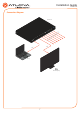
Panel Descriptions
11 12