Two-Input Wallplate Switcher for HDMI and VGA with Ethernet-Enabled HDBaseT Output AT-HDVS-200-TX-WP AT-HDVS-200-TX-WP-BLK Atlona Manuals Switchers
Version Information Version Release Date Notes 1 01/16 Initial release 2 07/17 New format AT-HDVS-200-TX-WP / AT-HDVS-200-TX-WP-BLK 2
Welcome to Atlona! Thank you for purchasing this Atlona product. We hope you enjoy it and will take a extra few moments to register your new purchase. Registration only takes a few minutes and protects this product against theft or loss. In addition, you will receive notifications of product updates and firmware. Atlona product registration is voluntary and failure to register will not affect the product warranty. To register your product, go to http://www.atlona.
Atlona, Inc. (“Atlona”) Limited Product Warranty Coverage Atlona warrants its products will substantially perform to their published specifications and will be free from defects in materials and workmanship under normal use, conditions and service.
Atlona, Inc. (“Atlona”) Limited Product Warranty • Damage, deterioration or malfunction resulting from the installation or removal of this product from any installation, any unauthorized tampering with this product, any repairs attempted by anyone unauthorized by Atlona to make such repairs, or any other cause which does not relate directly to a defect in materials and/or workmanship of this product.
Important Safety Information CAUTION RISK OF ELECTRIC SHOCK DO NOT OPEN CAUTION: TO REDUCT THE RISK OF ELECTRIC SHOCK DO NOT OPEN ENCLOSURE OR EXPOSE TO RAIN OR MOISTURE. NO USER-SERVICEABLE PARTS INSIDE REFER SERVICING TO QUALIFIED SERVICE PERSONNEL. The exclamation point within an equilateral triangle is intended to alert the user to the presence of important operating and maintenance instructions in the literature accompanying the product.
Table of Contents Introduction 8 Features 8 Package Contents 8 Panel Description 9 Installation RS-232 Connector Connection Instructions Faceplate Removal and Assembly Connection Diagram IP Configuration Using the Front Panel Using Commands Using the Web GUI 10 10 10 11 12 13 13 13 14 The Web GUI Introduction to the Web GUI Menu Bar Toggles Sliders Buttons Info page Video page Audio page Display page CEC System Settings TCP/IP Settings of Controlled Devices RS-232 / IP Commands RS-232 page EDID pa
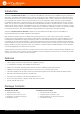
Introduction The Atlona AT-HDVS-200-TX-WP is a 2×1 switcher and HDBaseT transmitter with an HDMI input plus a VGA input with audio. The HDVS-200-TX-WP features a US two-gang, Decora-style wallplate form factor. Video signals up to 4K/UHD @ 60 Hz with 4:2:0 chroma subsampling, plus embedded audio, control, and Ethernet can be transmitted up to 330 feet (100 meters). The two-channel audio input can be assigned to either video input and embedded for HDBaseT transmission.
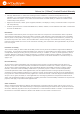
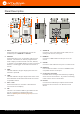
Panel Description 7 5 INPUT VOL+ DISPLAY VOL- 10 8 1 2 3 4 AUDIO IN HDMI IN RS-232 TX RX PWR LINK Front FW 6 VGA IN 9 Left Rear 1 INPUT Press this button to toggle between each of the available inputs: HDMI IN and VGA IN. 2 DISPLAY 8 Press this button to turn on/off video output for the switcher.
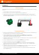
Installation RS-232 Connector The AT-HDVS-200-TX-WP provides RS-232 control between an automation system and an RS-232 device. This step is optional. 1. Use wire strippers to remove a portion of the cable jacket. 2. Remove at least 3/16” (5 mm) from the insulation of the RX, TX, and GND wires. 3. Insert the TX, RX, and GND wires into correct terminal on the included Phoenix block. If using non-tinned stranded wire, presss the orange tab, above the terminal, while inserting the exposed wire.
Installation Faceplate Removal and Assembly The AT-HDVS-200-TX-WP comes with an additional faceplate, which allows an Ethernet cable to be connected through the front panel. Removal of the faceplate requires that the AT-HDVS-200-TX-WP be removed from the electrical box or mud ring. 1. Remove the wall plate from the electrical box and slide out the AT-HDVS-200-TX-WP assembly, as shown.
Installation Connection Diagram io ud A io ud A ier A TPA 10 0 Am -G 2 plif dio Au ric ne EMS GeKER SYST TE MU M IC SPEA 2 RS-23Rx BA TR EB LE SS E LIN 1 Tx 2 T INPU NO MO IR E DG BRI mm 3.
Installation IP Configuration The AT-HDVS-200-TX-WP is shipped with DHCP enabled. Once connected to a network, the DHCP server (if available), will automatically assign an IP address to the unit. Use an IP scanner, along with the MAC address on the back the unit, to identify both the unit and its IP address on the network. If a static IP address is desired, the unit can be switched to static IP mode. Use one of the following procedures to switch between DHCP and static IP mode.
Installation 3. Execute the IPStatic command. This command requires three arguments: the desired IP address of the AT-HDVS-200-TX-WP, the subnet mask, and the gateway address. All arguments must be entered in dotdecimal notation. The following is an example: IPStatic 192.168.1.112 255.255.255.0 192.168.1.1 • Setting DHCP mode 1. Connect to the AT-HDVS-200-TX-WP using RS-232 or Telnet. 2. At the command line, execute the IPDHCP command using the on argument, as shown. All characters are case-sensitive.
Installation 4. Click the IP Mode toggle to switch between the DHCP and STATIC IP setting. When set to STATIC IP, the IP, Netmask, and Gateway fields can be modified. 5. Click the Save button to save the changes.
The Web GUI Introduction to the Web GUI The AT-HDVS-200-TX-WP includes a built-in web GUI. Atlona recommends that the web GUI be used to set up the AT-HDVS-200-TX-WP, as it provides intuitive management of all features. The AT-HDVS-200-TX-WP is shipped with DHCP enabled. Once connected to a network, the DHCP server will automatically assign an IP address to the unit. Use an IP scanner to determine the IP address of the AT-HDVS-200TX-WP. If a static IP address is desired, refer to IP Configuration (page 13).
The Web GUI 4. Type root, using lower-case characters, in the Username field. 5. Type Atlona in the Password field. This is the default password. The password field is case-sensitive. When the password is entered, it will be masked. The password can be changed, if desired. Refer to the Config page (page 30) for more information. 6. Click the Submit button or press the ENTER key on the keyboard. 7. The Info page will be displayed. Menu Bar The dark-colored bar, near the top of the screen, is the menu bar.
The Web GUI In this example, clicking Video, in the menu bar, will display the Video page. Toggles Several settings within the Web GUI use toggles, which enable, disable, or assign one of two settings. Generally, when the toggle is blue, it means that the feature is enabled or ON. If a feature is disabled, then the toggle will appear gray and be labeled as OFF.
The Web GUI Buttons Buttons are used to execute an action or setting. Several pages within the Web GUI include a Save button. Clicking the Save button will apply and save all settings in the current page. Other buttons, such as the Factory Defaults button, under the System page, will reset the AT-HDVS-200-TX-WP to factory-default settings.
The Web GUI Info page After logging in, the Info page will be displayed. The Info page provides basic information about the receiver, including the model name, software version, input video timing, and the device being using as the transmitter. Receiver name Model Name The model SKU of this product. Software Version The version of firmware that the AT-HDVS-200-TX-WP is running. Always make sure to check the AT-HDVS-200-TXWP product page, on the Atlona web site, for the latest version of firmware.
The Web GUI Video page Input Selection Click this drop-down list to select the desired input. VGA Adjust In most situations, adjustment of the VGA signal should not necessary. However, if the VGA signal does not appear correctly, click the Adjust button to automatically correct the clock and phase. Auto Switch Three controls are available under the Auto Switch feature. • Click the Auto Switch mode toggle to enable or disable auto-switching.
The Web GUI Audio page HDMI Audio These drop-down lists are only available when the system is in kit mode. Refer to Kit Mode (page 33) for more information. Audio Freerun Status Audio can be passed, without the presence of a video signal. To enable this functionality, click the Audio Freerun Status toggle to the ON position. To pass both video and audio, this toggle must be set to the OFF position. IMPORTANT: Setting the Audio Freerun Status to ON is not recommended.
The Web GUI L/R Audio Click this toggle to the OFF position to mute only the analog audio. Output Click and drag this slider bar to adjust the output audio volume. Range: -80 to 0. Output Bass Click and drag this slider bar to adjust the bass of the audio output. Range: -12 to 15. Output Treble Click and drag this slider bar to adjust the treble of the audio output. Range: -12 to 15.
The Web GUI Display page CEC CEC Command Click the ON button to send the power-on command to the display device. Click the OFF button to toggle the power state to off. Consumer Electronics Control (CEC): Atlona has confirmed proper CEC functionality with several current models of Samsung, Panasonic, and Sony displays. However, it is not guaranteed that CEC will work with all displays. Many manufacturers do not support the CEC “off” command, and older displays use proprietary commands.
The Web GUI System Settings Display Auto Power On Sends the command to power-on the display when an A/V signal is detected. Click the toggle to enable or disable this feature. Otherwise, set to DISABLED. Display Auto Power Off Sends the command to power-off the display when an A/V signal is no longer present. Click the toggle to enable or disable this feature. Otherwise, set to DISABLED.
The Web GUI Display Mode Click this drop-down list to select the display mode. Setting Description DispSW AVon Display switches on/off, source audio/video signal always on. DispSW AVSW Display switches on/off, source audio/video signal switches on/off. AV SW Display is always on, source audio/video signal switches on/off Volume / Mute Click this drop-down list to select the control method for volume and muting.
The Web GUI RS-232 / IP Commands Send Mode Sets the type of commands that are sent to the display, either ASCII or Hex. On/Off/Volume+/Volume-/Mute • Set command Enter the command in this field. • Feedback Enter the feedback string in this field. • CR-LF Click this drop-down list to select the desired end-of-line characters to be sent.
The Web GUI RS-232 page Zone When the AT-HDVS-200-TX-WP is connected to the AT-HDVS-200-RX, the system is placed in kit mode. In this mode, the drop-down list boxes will be disabled and the HDBaseT baud rate will be locked at 115200. If the AT-HDVS-200-TX-WP is connected to another HDBaseT device, such as the AT-UHD-CLSO-824, each of these drop-down list boxes can be set to the baud rate of the HDBaseT RS-232 settings on the corresponding device.
The Web GUI EDID page Perfer Timing (HDMI) Adjusts the brightness setting of the output signal. Range: 0 - 128. Prefer Timing (VGA) Adjusts the contrast setting of the output signal. Contrast is the difference between the lightest and darkest area of an image. Range: 0 - 128. Input HDCP Provides control over the transmission of HDCP content for the HDMI IN port. The following options are available: • Compliant - Forces detection of HDCP-compliant sink devices.
The Web GUI Config page Old Username This field cannot be changed. “root” is the administrator user. Old Password Enter the current password for the “root” username in this field. The default password is “Atlona”. New Username This field cannot be changed. Save Click this button to save all changes. New Password Enter the new password fro the “root” username in this field. Confirm New Password Verify the new password by retyping it in this field. All User Login Settings • Username Displays the username.
The Web GUI System page IP Mode Click this toggle to set the IP mode of the AT-HDVS-200-TX-WP. By default, the AT-HDVS-200-TX-WP is set to DHCP mode. Available settings: STATIC IP, DHCP. IP Enter the IP address of the AT-HDVS-200-TX-WP in this field. This field will only be available if IP Mode is set to STATIC IP. The default IP address is 192.168.1.254. Netmask Enter the subnet mask in this field. This field will only be available if IP Mode is set to STATIC IP.
The Web GUI Reset to Default Click the Factory Default button to set the AT-HDVS-200-TX-WP to factory-default settings. Firmware Update Click the Choose File button to select the firmware file, when upgrading the firmware on the AT-HDVS-200-TX-WP. Once the firmware file is selected, click the Update button. Refer to Updating the Firmware (page 67) for more information. Valens Update Click the Choose File button to select the Valens firmware file, when upgrading the Valens chip on the AT-HDVS-200TX-WP.
The Web GUI Kit Mode If the AT-HDVS-200-TX-WP is connected to the AT-HDVS-200-RX, the system will be placed in kit mode. This section covers features only available in kit mode. Note that when in kit mode, the text “GENERAL” is replaced with the name of receiver that is connected. Video Receiver Aspect Output Resolution Picture group Aspect Click the Aspect drop-down list and select the desired aspect ratio. Aspect Ratio Description Full The input signal is adjusted to fill the screen.
The Web GUI Output Resolution Click the Output Resolution drop-down list and select the desired resolution. The default resolution is 720p. Output Resolutions 800x600@60 1024x768@60 1280x800@60 1280x1024@60 1366x768@60 1400x1050@60 1600x900@60RB 1600x1200@60 1680x1050@60 1920x1200@60RB 720p25 720p29.97 720p30 720p50 720p59.94 720p60 1080i50 1080i59.94 1080i60 1080p23.98 1080p24 1080p25 1080p29.97 1080p30 1080p50 1080p59.
The Web GUI Audio HDMI Audio (mute) HDMI Audio (audio select) L/R Audio (mute) HDMI Audio Click the drop-down list for HDMI 1 and HDMI 2 to select the input audio source used by each HDMI input. Setting Description Auto Automatically detects the audio source. If an HDMI cable with embedded audio is connected, the system will use the digital audio on the HDMI cable.
The Web GUI RS-232 RX RS-232 Zone 1 RX RS-232 Zone 1 Each of these drop-down lists refer to the setting for the RS-232 1 port on the receiver. Click the Save button to save the settings. Setting Description Baud rate Sets the baud rate. The following options are available: 2400, 9600, 19200, 38400, 56000, 57600, 115200. Data bit Sets the number of data bits used to represent each character of data. The following options are available: 7 or 8.
Commands The following tables provide an alphabetical list of commands available on the AT-HDVS-200-TX-WP. All commands are case-sensitive and must be entered as documented. If the command fails or is entered incorrectly, then the feedback is “Command FAILED”. IMPORTANT: Each command is terminated with a carriage-return (0x0d) and the feedback is terminated with a carriage-return and line-feed (0x0a).
Commands Command Description DispKeyLock Locks or unlocks the DISPLAY button on the front panel Display Send the command to the display device using the current protocol DispRS Sets the display command type to RS-232 FreeRun Enables or disables “audio-only” from the transmitter to the receiver HDCPSet Sets the HDCP reporting mode for the HDMI IN 1 port HDMIAUD Enables or disables audio on the HDMI output HDVS Displays the model number of the connected receiver help Displays the list of avai
Commands Command Description SetEnd Sets the end-character delimiter for the specified command SetFbVerify Sets the feedback verification state SetStrgType Sets the type of command string SHARP Sets the picture sharpness System Displays system information about the AT-HDVS-200-TX-WP TREBLE Increases or decreases the treble on the output TrigCEC Triggers the stored CEC command TrigIP Triggers the stored IP command TrigRS Triggers the stored RS-232 command Type Displays the model of the t
Commands AnaGain Sets the gain of the analog input. Syntax AnaGain X Parameter Description Range X Audio gain 0 ... 16 Example AnaGain 1 Feedback AnaGain 1 APwrOffTime Set the time interval, in seconds, before the command to power-off the display is sent, once an A/V signal is no longer detected. Use the sta argument to display the current APwrOffTime setting. Syntax APwrOffTime X Parameter Description Range X Time interval 5 ...
Commands ASwFstTime Sets the time interval, in seconds, before the unit switches to the input used by a newly-powered or connected device. Use the sta argument to display the current setting. Syntax ASwFstTime X Parameter Description Range X Time interval 10 ... 600, sta Example ASwFstTime 10 Feedback ASwFstTime 10 ASwOutTime Sets the time interval, in seconds, before the unit automatically switches to another active input if no signal is received from the current input.
Commands AudioSrc Sets the audio source for the each HDMI input. Parameter X specifies the HDMI port. Parameter Y specifies the type of audio that will be used. Do not include a space between the AudioSrc command and the first argument. Use the sta argument, for parameter Y, to display the current setting of the specified port. Syntax AudioSrcX Y Parameter Description Range X HDMI IN port 1 ...
Commands AutoPwrMode Sets the display mode for auto-power on and off. Syntax AutoPwrMode X Parameter Description Range X Value DISPAVON, DISPAVSW, AVSW, sta Example AutoPwrMode DISPAVON Feedback AutoPwrMode DISPAVON AutoSW Enables or disables auto switching or display auto switching status. Syntax AutoSW X Parameter Description Range X Value on, off, sta Example AutoSW on Feedback AutoSW on BASS Increases or decreases the amount of bass on the output.
Commands Blink Enables or disables blinking of the DN button on the front panel. When set to on, the DN button will flash red and can be used to physically identify the unit on a network. The DN button will flash until the Blink off command is executed. on = enables DN button blinking; off = disables DN button blinking; sta = displays the current setting. The default setting is off.
Commands CliIPAddr Sets the IP address of the controlled device. The IP address must be specified in dot-decimal notation. Use the sta argument to display the IP address of the device. DHCP must be disabled before using this command. Refer to the IPDHCP command for more information. Syntax CliIPAddr X Parameter Description Range X IP address 0 ... 255 (per byte) Example CliIPAddr 192.168.1.61 Feedback CliIPAddr 192.168.1.61 CliMode Sets the login mode of the controlled device.
Commands CliPort Sets the listening port for the controlled device. Use the sta argument to display the current listening port. The default port is 23. Syntax CliPort X Parameter Description Range X Port 0 ... 65535, sta Example CliPort 30 Feedback CliPort 30 CliUser Sets the username for the controlled device. Execute the CliUser command without arguments to display the current username.
Commands CSpara Sets the baud rate, data bits, parity bit, and stop bits for the serial device. Use the sta argument to display the current serial port settings. Each argument must be separated by a comma; no spaces are permitted. Brackets must be used when executing this command.
Commands DispBtn Simulates pressing the DISPLAY button on the front panel, activating the display mode and RS-232/CEC/IP display control commands. on = simulates pressing the DISPLAY button to the “on” state, off = simulates pressing the DISPLAY button to the “off” state, tog = reverses the current state of the DISPLAY button, sta = displays the current setting.
Commands DispKeyLock Locks the DISPLAY button on the front panel, preventing it from being accidentally activated. on = locks the DISPLAY button, off = unlocks the DISPLAY button, sta = displays the current setting. Syntax DispKeyLock X Parameter Description Range X Setting on, off, sta Example DispKeyLock on Feedback DispKeyLock on Display Sends the “on” or “off” command to the display using the current protocol. Use the sta argument to display the current setting.
Commands FreeRun Enables or disables only audio to be sent from the transmitter to the receiver. on = enable, off = disable, sta = displays the current setting. Syntax FreeRun X Parameter Description Range X Setting on, off, sta Example FreeRun on Feedback FreeRun on IMPORTANT: Setting the Audio Freerun Status to ON is not recommended. When set to ON, both video auto switching and display control are disabled. HDCPSet Set the HDCP reporting mode of the specified HDMI IN port.
Commands HDMIAUD Enables or disables audio on the HDMI output. on = enables HDMI audio output; off = disables HDMI audio output; sta = displays the current HDMIAUD setting. Syntax HDMIAUD Parameter Description Range X Value on, off, sta Example HDMIAUD off Feedback HDMIAUD off HDVS Displays the model number of the connected receiver. The sta argument must be provided. If no receiver is connected, this command will return Null.
Commands HUE Sets the picture hue. Use the sta argument to display the current HUE value. Syntax HUE X Parameter Description Range X Value 0 ... 100, sta Example HUE 40 Feedback HUE 40 Input Sets the active input. When specifying an HDMI input, the number of the input must also be specified. Do not add a space between the HDMI argument and the input number. Use the sta argument to display the current setting.
Commands IPCFG Displays the current network settings for the AT-HDVS-200-TX-WP. Syntax IPCFG This command does not require any parameters Example IPCFG Feedback IP Addr: 10.0.1.101 Netmask: 255.255.255.0 Gateway: 10.0.1.1 IP Port: 23 IPDelUser Deletes the specified TCP/IP user. This command performs the same function as removing a user within the Config page of the web GUI. Refer to the Config page (page 30) for more information.
Commands IPLogin Enables or disables the use of login credentials when starting a Telnet session on the AT-HDVS-200-TX-WP. If this feature is set to on, then the AT-HDVS-200-TX-WP will prompt for both the username and password. Use the same credentials as the web GUI. on = login credentials required; off = no login required; sta = displays the current setting.
Commands IPTimeout Specifies the time interval of inactivity before the Telnet session is automatically closed. Syntax IPTimeout X Parameter Description Range X Interval (in seconds) 1 ... 60000 Example IPTimeout 300 Feedback IPTimeout 300 LRAUD Enables or disables the L/R audio output. on = enables L/R audio out, off = disables L/R audio out, sta = displays the current setting.
Commands PictureRst Resets the picture settings to factory-default settings. This command does not reset the unit to factory-default settings. Refer to the Mreset command for more information. Syntax PictureRst This command does not require any parameters Example PictureRst Feedback PictureRst PrefTimg Sets the preferred input timing. Specify a value from 0 to 8. Syntax PrefTimg X Parameter Description Range X Timing 0 ...
Commands ProjWarmUpT Sets the display warm-up interval, in seconds. During this time, the display will not accept any commands until the “power on” command has been processed. Use the sta argument to display the current setting. Syntax ProjSWMode X Parameter Description Range X Time interval 0 ... 300, sta Example ProjWarmUpT 120 Feedback ProjSWMode 120 RS232para Sets the baud rate, data bits, parity bit, and stop bits for the RS-232 port on the AT-HDVS-200-TX-WP.
Commands RS232zone Sends commands to the connected display. Refer to the User Manual of the display device for a list of available commands. Brackets must be used when specifing the command argument. The command line must not contain any spaces. Syntax RS232zone[X] Parameter Description Range X Command String Example RS232zone[command] Feedback RS232zone[command] RxRSparaZ Sets the baud rate, data bits, parity bit, and stop bits for the RS-232 1 port on the AT-HDVS-200-RX.
Commands SATRT Sets the picture color saturation value. Use the sta argument to display the current setting. Syntax SATRT X Parameter Description Range X Saturation 0 ... 100, sta Example SATRT 50 Feedback SATRT 50 SetCmd Assigns an RS-232 or IP command to the specified button on the front panel.
Commands SetFbVerify Sets the feedback verification state. on = the AT-HDVS-200-TX-WP will make four attempts to send the command. If the feedback string is not acknowledged after the fourth attempt, the process will fail. off = sends the command and ignores the feedback string. Use the sta argument to display the current setting. Syntax SetFbVerify X Parameter Description Range X Value on, off, sta Example SetFbVerify on Feedback SetFbVerify on SetStrgType Sets the type of command string.
Commands System Displays system information about the AT-HDVS-200-TX-WP. The sta argument must be specified. Syntax System X Parameter Description Range X Status sta Example System sta Feedback Model: AT-HDVS-200-TX-WP MAC Addr: b8-98-b0-00-10-e6 Address Type: DHCP IP Addr: 10.0.1.161 Netmask: 255.255.255.0 Gateway: 10.0.1.1 HTTP Port: 80 Telnet Port: 23 Firmware: 1.1.28 On/Up Time
- : 00 00:53:31 TREBLE Increases or decreases the amount of treble.
Commands TrigCEC Trigger the specified command to the display using CEC. Syntax TrigCEC X Parameter Description Range X Value on, off, vol+, vol-, mute Example TrigCEC on Feedback TrigCEC on TrigIP Trigger the specified command to the display using IP. Syntax TrigIP X Parameter Description Range X Value on, off, vol+, vol-, mute Example TrigIP vol+ Feedback TrigIP vol+ TrigRS Trigger the specified command to the display using RS-232.
Commands Type Displays the model information of the AT-HDVS-200-TX-WP. Syntax Type This command does not require any parameters Example Type Feedback AT-HDVS-200-TX-WP Update Places the AT-HDVS-200-TX-WP in firmware update mode. MCU = will update the MCU firmware, VSTX = update the Valens firmware. When placing the unit in update mode, it is recommended that the Using USB (page 68) procedure, outlined under Updating the Firmware (page 67), be used.
Commands VGAAuto Executes the VGA auto-adjust. This command automatically adjusts the phase and clock of the VGA signal. Syntax VGAAuto This command does not require any parameters Example VGAAuto Feedback VGAAuto VGAPrefT Sets the preferred VGA input timing. Specify a value from 0 to 8. Syntax PrefTimg X Parameter Description Range X Timing 0 ...
Commands VidOutRes Sets the video output resolution. Use the sta argument to display the current video output resolution. Syntax VidOutRes Parameter Description Range X Value 0 ... 28, sta Output Resolution List 0 = 800x600@60 1 = 1024x768@60 2 = 1280x800@60 3 = 1280x1024@60 4 = 1366x768@60 5 = 1400x1050 6 = 1600x900@60RB 7 = 1600x1200@60 8 = 1680x1050@60 9 = 1920x1200@60RB 10 = 720p25 11 = 720p29.97 12 = 720p30 13 = 720p50 Example VidOutRes 26 14 = 720p59.94 15 = 720p60 16 = 1080i50 17 = 1080i59.
Commands VOUT Increases or decreases the audio output volume. In addition to specifying an integer value, the + and - arguments can be used, by themselves, to increase or decrease the volume by 1 value, respectively. To display the current value, execute the VOUT command without any arguments. Syntax VOUT Parameter Description Range X Value -80 ... 0 Example VOUT 4 VOUT + Feedback VOUT 4 VOUT 5 VOUTMute Mutes or unmutes the audio.
Appendix Updating the Firmware Updating the firmware can be completed using either the USB interface or the web GUI. Atlona recommends using the web GUI for updating the firmware. However, if a network connection is not available, the AT-HDVS-200TX-WP firmware can be updated using a USB-A to USB mini-B cable Using the Web GUI Requirements • • • AT-HDVS-200-TX-WP Firmware file Computer 1.
Appendix 6. The following message box will be displayed. 7. Click the OK button to begin the firmware update process. Click the Cancel button to cancel the process. 8. After the firmware update process is complete, the Login screen will be displayed. Using USB Requirements • • • • AT-HDVS-200-TX-WP Firmware file Computer running Windows USB-A to USB mini-B cable INPUT VOL+ DISPLAY VOL- AUDIO IN HDMI IN 1. Disconnect power from the AT-HDVS-200-TX-WP. 2.
Appendix 3. Press and hold the INPUT button, on the front panel, while connecting power to the AT-HDVS-200-TX-WP. 4. The USB UPDATE folder will be displayed. If this folder is not displayed, automatically, select the USB UPDATE drive from Windows Explorer. 7. Delete all files from the USB UPDATE drive, if any are present. 8. Drag-and-drop the firmware file to the drive. 9. After the file has been copied, disconnect the USB cable from both the computer and the AT-HDVS-200-TX-WP. 10.
Appendix Default Settings The following tables list the factory-default settings for the AT-HDVS-200-TX-WP.
Appendix Specifications Video HD/SD 4096×2160@24/25/30/50*/60Hz*, 3840×2160@24/25/30/50*/60Hz*, 2048x1080p, 1080p@23.98/24/25/29.97/30/50/59.94/60Hz, 1080i@50/59.94/60Hz, 720p@50/59.
Appendix Power Consumption TBD Dimensions Wall 2 gang Weight Pounds Kilograms Device TBD TBD Certification Unit CE, FCC AT-HDVS-200-TX-WP / AT-HDVS-200-TX-WP-BLK 72
Index A Aspect ratio 33 Audio muting 66 passing only audio 22 B Bass adjusting 22, 23 Brightness 34, 36 C CEC compatibility 24 ON/OFF 24 Commands AnaGain 40 APwrOffTime 40 Aspect 40 ASwFstTime 41 ASwOutTime 41 ASwPrePort 41 AudioSrc 42 AutoDispOff 42 AutoDispOn 42 AutoPwrMode 43 AutoSW 43 BASS 43 Blink 44 Broadcast 44 BRT 44 CliIPAddr 45 CliMode 45 CliPass 45 CliPort 46 CliUser 46 CSpara 47 CTRST 47 DispBtn 48, 49 DispCEC 48 DispIP 48 DispKeyLock 49 DispRS 49 DisWarmUp 48, 49 FreeRun 50 HDCPSet 50 HDMIAUD
Index S Safety information 6 Saturation 34 Sharpness 34, 60 Specifications 71 Static IP 31, 54 Subnet mask 31 Switching auto 21 T Telnet listening port 31 login mode 31 timeout 31 Timer auto power-off 25 display warm-up 25 lamp cool down 25 Treble adjusting 22, 23 U Users adding 30, 52 editing 30 primary user name 17 removing 30, 53 V VGA signal adjustment 21 Volume adjusting 66 W Warranty 4 Web GUI 16 AT-HDVS-200-TX-WP / AT-HDVS-200-TX-WP-BLK 74
atlona.com • 408.962.0515 • 877.536.3976 © 2018 Atlona Inc. All rights reserved. “Atlona” and the Atlona logo are registered trademarks of Atlona Inc. All other brand names and trademarks or registered trademarks are the property of their respective owners. Pricing, specifications and availability subject to change without notice. Actual products, product images, and online product images may vary from images shown here.