4K / UHD Three-Input Switcher for HDMI and USB-C with HDBaseT™ and HDMI Outputs AT-OME-ST31A Atlona Manuals Switchers
Version Information Version Release Date Notes 1 May 2019 Initial release AT-OME-ST31A 2
Welcome to Atlona! Thank you for purchasing this Atlona product. We hope you enjoy it and will take a extra few moments to register your new purchase. Registration only takes a few minutes and protects this product against theft or loss. In addition, you will receive notifications of product updates and firmware. Atlona product registration is voluntary and failure to register will not affect the product warranty. To register your product, go to http://atlona.
Atlona, Inc. (“Atlona”) Limited Product Warranty Coverage Atlona warrants its products will substantially perform to their published specifications and will be free from defects in materials and workmanship under normal use, conditions and service.
Atlona, Inc. (“Atlona”) Limited Product Warranty • Damage, deterioration or malfunction resulting from the installation or removal of this product from any installation, any unauthorized tampering with this product, any repairs attempted by anyone unauthorized by Atlona to make such repairs, or any other cause which does not relate directly to a defect in materials and/or workmanship of this product.
Important Safety Information CAUTION RISK OF ELECTRIC SHOCK DO NOT OPEN CAUTION: TO REDUCT THE RISK OF ELECTRIC SHOCK DO NOT OPEN ENCLOSURE OR EXPOSE TO RAIN OR MOISTURE. NO USER-SERVICEABLE PARTS INSIDE REFER SERVICING TO QUALIFIED SERVICE PERSONNEL. The exclamation point within an equilateral triangle is intended to alert the user to the presence of important operating and maintenance instructions in the literature accompanying the product.
Table of Contents Introduction 8 Features 8 Package Contents 8 Panel Description 9 Installation Connection Instructions Notes on Scaling Connection Diagram IP Configuration Switching the IP Mode Using the Front Panel Setting the IP Address using the Web Server Auto IP Mode Displaying the IP Address 10 10 11 12 13 13 13 14 14 Device Operation LED Indicators Input Switching Manual Switching HDCP Content Controlling Audio Audio Output Muting De-Embedding Audio Password Management Resetting to Factory
Introduction The Atlona AT-OME-ST31A is a 3×1 switcher and HDBaseT transmitter with HDMI and USB-C inputs. Part of the Omega™ Series of integration products for modern AV communications and collaboration, it features mirrored HDMI and HDBaseT outputs, two-channel audio de-embedding to an analog balanced audio output, and is HDCP 2.2 compliant. The USB-C input is ideal for AV interfacing for newer Mac®, Chromebook™, and Windows® PCs, as well as smartphones and tablets.
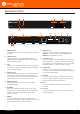
Panel Description 1 3 4 5 AT-OME-ST31A 1 2 3 PWR LINK OMEGA TM FW INPUT 2 6 IP MODE RESET IP MODE RESET 1 LINK FW 8 2 2 Front INPUT 9 3 INPUT 1 AT-OME-ST31A 1 2 3 PWR OMEGA TM DISPLAY L 10 R DISPLAY 11 12 OUTPUT AUDIO OUT L R RS-232 LAN OUTPUT AUDIO OUT RS-232 LAN AT-OME-ST31A 13 AT-OME-ST31A DC 24V 3 INPUT DC 24V Rear 7 1 PWR Indicator This LED indicator glows solid green when the unit is powered.
Installation Connection Instructions 1. Connect HDMI cables from HD/UHD sources to INPUT 2 and INPUT 3. 2. Connect a USB-C cable from a source to INPUT 1 on the switcher. 3. Connect an Ethernet cable, from the HDBaseT port to a compatible HDBaseT receiver. NOTE: The AT-OME-ST31A is powered by a receiver unit using PoE over HDBaseT. If a PoE over HDBaseT receiver is not used, then the AT-OME-ST31A must be powered using the optional 24 V DC power supply* (not included).
Installation Notes on Scaling The following section provides important information about how the AT-OME-ST31A processes 4K (UHD) video signals. 1. The HDMI OUTPUT port supports up to 4K @ 60 Hz, 12-bit, with HDR. 2. If the source is 4K, and the HDMI OUTPUT port is connected to a 1080p (not 4K-capable) display, then the output will be down-scaled as follows: Input Output 4K @ 24 Hz 1080p @ 24 Hz 4K @ 30 Hz 1080p @ 30 Hz 4K @ 60 Hz, 4:2:0 1080p @ 60 Hz, YUV/RGB 4:4:4 3.
Installation Connection Diagram H D M I Laptop H D M I Laptop Et h er ne t LAN A T31 E-S -OM AT T TES 1 2 3 R PW K FW TM EG OM I M AT-OME-ST31A H D B as eT U D H SB -C LIN A UT INP Display T MI OU HD seT IN Ba HD RX TX 2 -23 RS V DC 48 I M D H AT-UHD-EX-100CE-RX-PSE Display AT-OME-ST31A 12
Installation IP Configuration The AT-OME-ST31A is shipped with DHCP enabled. Once connected to a network, the DHCP server (if available), will automatically assign an IP address to the unit. If the AT-OME-ST31A is unable to detect a DHCP server within 15 seconds, then the unit will use a self-assigned IP address within the range of 169.254.xxx.xxx. Use an IP scanner, along with the MAC address on the bottom of the unit, to identify the unit on the network.
Installation Auto IP Mode If the AT-OME-ST31A is unable to detect a DHCP server within 15 seconds, then the unit will use a self-assigned IP address within the range of 169.254.xxx.xxx. If this occurs, connect the AT-OME-ST31A to a computer running Microsoft Windows® and follow the procedure below. 1. Click Start > Settings > Control Panel > Network and Sharing Center. 2. Click Change adapter settings. 3.
Device Operation LED Indicators The LED indicators on both the front and rear of the unit provide basic information on the current status of the ATOME-ST31A. LED PWR LINK 1, 2, 3 IP MODE RESET Description Solid green • Unit is receiving power using the optional 24 V DC power supply (not included) or the Ethernet cable connected between the HDBaseT OUTPUT port and a PoE over HDBaseT-compatible receiver. Off • Unit is not powered.
Device Operation Input Switching Switching between any of the three input ports can be performed either manually or automatically. The following section covers both methods. Manual Switching 1. Press and release the INPUT button on the front panel to cycle between INPUT 1 (USB-C), INPUT 2 (HDMI), and INPUT 3 (HDMI) inputs. The USB-C input (INPUT 1) is the factory-default setting.
Device Operation HDCP Content Normally, if a source is transmitting HDCP content to a display that is not HDCP-compatible, then the resulting image on the display can be “snow”, image flickering, or no picture. For example, in the illustration below, a laptop source is connected to the AT-OME-ST31A. A non-compliant display is connected to a receiver, which is connected to the AT-OME-ST31A using HDBaseT.
Device Operation Controlling Audio The AT-OME-ST31A provides complete control over both audio muting and audio input sources. Audio muting can be controlled on both HDMI and HDBaseT outputs. Analog audio can also be embedded on the HDBaseT or HDMI outputs using a 3.5 mm mini-stereo cable. Audio Output Muting 1. Open the desired web browser and enter the IP address of the AT-OME-ST31A. 2. Log in as the admin user with the required credentials.
Device Operation 4. Locate the Audio section. Any of the three inputs can be set to receive either the existing digital audio from the source, or an external analog source. 5. Set the Analog Output toggle switch to the ON position. Audio from the source will be de-embedded and output on the AUDIO OUT port.
Device Operation Password Management The AT-OME-ST31A allows the administrator password to be changed. The password applies to both the web interface and Telnet sessions. 1. Open the desired web browser and enter the IP address of the AT-OME-ST31A. 2. Log in as the admin user with the required credentials. The factory-default username and password for the admin user are listed below: Username: admin Password: Atlona 3. Click the Config tab. 4. Enter the current password in the Old Password field. 5.
Device Operation Resetting to Factory Defaults If necessary, the AT-OME-ST31A can be reset to factory-default settings. Note that the AT-OME-ST31A will be placed in DHCP mode, as part of the reset procedure. The AT-OME-ST31A can also be reset through the web server. Both procedures will be covered in this section. Using the Rear Panel AT-OME-ST31A 1. Press and hold the RESET button on the rear panel for approximately 101 seconds. PWR 2 LINK 2.
Configuration and Management Interfaces Introduction to the Web Server The AT-OME-ST31A includes a built-in web server. Atlona recommends that the web server be used to set up the AT-OME-ST31A, as it provides intuitive management of all features. Follow the instructions below to access the webGUI. 1. Make sure that an Ethernet cable is connected between the LAN port on the AT-OME-ST31A and the network. 2. Launch a web browser and enter the IP address of the unit.
Configuration and Management Interfaces 7. The Info page will be displayed. Menu Bar The dark-colored bar, near the top of the screen, is the menu bar. When the mouse is moved over each menu element, it will be highlighted in light orange. Once the desired menu element is highlighted, click the left mouse button to access the settings within the menu. Menu bar In this example, clicking A/V Settings, in the menu bar, will display the A/V Settings page.
Configuration and Management Interfaces Info Page After logging in, the Info page will be displayed. The Info page provides various information about the receiver, including the model name, software version, and video information. Model Name The model SKU of this product. Software Version The version of firmware that the AT-OME-ST31A is running. Always make sure to check the AT-OME-ST31A product page, on the Atlona web site, for the latest version of firmware.
Configuration and Management Interfaces A/V Settings Page The A/V Settings page is divided into three sections: Video, Audio, and HDCP. The Video section allows the preferred input timing to be selected as well as whether or not HDCP content is allowed to pass. The Audio section provides options to control the output audio volume, muting, treble, and bass. The HDCP section provides management of HDCP and non-HDCP content. Input Selection Click this drop-down list to manually select the desired input.
Configuration and Management Interfaces Scaler Pass-Through Click this toggle switch to enable or disable the scaler pass-through feature. When set to the ON position, no scaler processing is used and the output resolution / timing will be the same as the input source. When disabled (OFF), 4K content will be down-scaled to 1080p. By default, this feature is set to the OFF position, which provides scaling capability. Audio Manages audio settings for inputs and outputs.
Configuration and Management Interfaces Display Page CEC Command Click the ON button to send the power-on command to the display device. Click the OFF button to toggle the power state to off. Consumer Electronics Control (CEC): Atlona has confirmed proper CEC functionality with several current models of Samsung, Panasonic, and Sony displays. However, it is not guaranteed that CEC will work with all displays.
Configuration and Management Interfaces Control Type Sets the control method for sending commands. The following options are available: RS-232, IP, CEC. Setting Description RS-232 RS-232 is used to send commands. IP Commands are sent over IP. CEC Uses CEC to send commands. RS-232 / IP Commands Provides customization of RS-232 / IP control device commands. • Manufacturer Click this drop-down list to select the manufacturer of the control device. As of this writing, only Generic can be selected.
Configuration and Management Interfaces RS-232 Page RS-232 Parameter Setting This section allows the RS-232 settings to be specified for HDBaseT and Console. • RS232 over HDBaseT If the AT-OME-ST31A is connected to a device such as the AT-UHD-EX-100CE-RX-PSE, the drop-down list boxes will be disabled and the HDBaseT baud rate will be locked at 115200.
Configuration and Management Interfaces EDID Page EDID Settings Click these drop-down lists to select the desired EDID to be used for each input. The following EDID presets are available. When selecting an EDID, make sure that the display/sink device is capable of supporting the resolution/ timing. If the sink device is not able to support a feature, then the source will not be displayed. Selecting the Connected Display EDID will provide the most compatible settings for most displays.
Configuration and Management Interfaces Time Page SNTP Configuration Simple Network Time Protocol (SNTP) is a simplified version of the Network Time Protocol (NTP), and can be used to set the time for the unit. SNTP is used to receive time services from other servers. However, it cannot be used to provide time servers to other systems. • GMT Click this drop-down list to select the Greenwich Mean Time (GMT) for the current location. • NTP Server Enter the desired NTP server address in this field.
Configuration and Management Interfaces Config Page The Config page provides management of the administrator password. The administrator username (“admin”) cannot be changed. Old Username This field cannot be changed. “admin” is the administrator user. Old Password Enter the current password for the “admin” username in this field. The default password is “Atlona”. New Password Enter the new password fro the “admin” username in this field.
Configuration and Management Interfaces System Page The System page is divided into two sections: Network and System. The Network section allows configuration of the IP settings of the AT-OME-ST31A. The System section provides controls for resetting the AT-OME-ST31A to factory-default settings and updating the firmware. MAC Address This field displays the MAC address of the AT-OME-ST31A. IP Mode Click this toggle switch to set the AT-OME-ST31A to DHCP or STATIC IP mode. The default setting is DHCP mode.
Configuration and Management Interfaces Telnet Timeout Click this drop-down list to select the timeout interval, in seconds. Range is: 1 to 10000 seconds, or Never. Hostname Displays the hostname of the AT-OME-ST31A, as it would appear on a network. To change the hostname, type the new hostname in this field and click the Save button. Authentication Click this drop-down list to select the authentication method when using the 802.1x security protocol.
Solution Setup and Configuration Guide The following sections provide step-by-step instructions for the following topics: • • • Input Auto-Switching Display Control Control Mode Input Auto Switching The AT-OME-ST31A provides auto-switching capability. By default, this feature will automatically switch the input to the most recently-connected or powered source when a source is disconnected.
Solution Setup and Configuration Guide 6. Click the Auto Switch toggle button to enable (ON) or disable (OFF) auto-switching. 7. Click the Fallback Input drop-down list to select the desired mode of operation. Fallback Input Description USBC Automatically switches to USB-C. HDMI1 Automatically switches to HDMI 1. HDMI2 Automatically switches to HDMI 2. Previous (default setting) The switcher will return to the previous (last connected) input.
Solution Setup and Configuration Guide Display Control The AT-OME-ST31A provides both a LAN and RS-232 port, which allows commands to be sent from the AT-OMEST31A to a connected display over a serial cable or over Ethernet. No external control system is required. The DISPLAY button can be programmed to toggle power on the display, allowing for convenient control of the display device from the location of the source. Using RS-232 AT-OME-ST31A 1 1.
Solution Setup and Configuration Guide 7. Set the RS-232 settings for the display (sink) device, under the RS232 Console section. These settings must match the device settings for the display. Otherwise, RS-232 control will not function. Refer to the User Manual of the display device for information. 8. Click the Save button to commit changes. 9. Click Display in the menu bar. The Display page will be shown. 10. Under System Settings, click the Control Type drop-down list and select RS-232. 11.
Solution Setup and Configuration Guide 13. Continue fine-tuning the device selection by clicking the Products and Model drop-down lists. Once all fields have been set to the proper values, the AT-OME-ST31A will populate the command fields with the proper values, based on the selected device. NOTE: If the manufacturer/model is not listed in the drop-down lists, then the command fields can be entered manually. Consult the User Manual for the display/sink device to obtain the correct command format. 14.
Solution Setup and Configuration Guide Using IP Instead of using a serial cable to send commands, this method uses an Ethernet cable to send commands from the AT-OME-ST31A to the display device. AT-OME-ST31A 1. Connect an Ethernet cable from the LAN port on the AT-HD-SC-500, to the LAN port on the display. 1 2 3 INPUT L OUTPUT DISPLAY to display AT-OME-ST31A R AUDIO OUT RS-232 LAN DC 24V 2. Launch a web browser. 3. In the address bar, type the IP address of the AT-HD-SC-500. 4.
Solution Setup and Configuration Guide 7. Under System Settings, click the Control Type drop-down list and select IP. 8. Locate the TCP/IP Settings of Controlled Device section and enter the following information: a. IP Mode If the device does not require a login, then set this drop-down value to Non-Login. If the device requires login credentials, select Login from the drop-down list.
Solution Setup and Configuration Guide 11. Continue fine-tuning the device selection by clicking the Products and Model drop-down lists. Once all fields have been set to the proper values, the AT-OME-ST31A will populate the command fields with the proper values, based on the selected device. NOTE: If the manufacturer/model is not listed in the drop-down lists, then the command fields can be entered manually. Consult the User Manual for the display/sink device to obtain the correct command format. 12.
Solution Setup and Configuration Guide Pass-through mode In pass-through mode, RS-232 commands are sent to the AT-OME-ST31A and then transmitted over HDBaseT to the receiver unit, and then to the display (sink) device. 1. Connect the RS-232 cable between the control system and the AT-OME-ST31A. 2. Connect an Ethernet cable from the desired HDBaseT OUT port to a receiver. 3. Connect an RS-232 cable between the display (sink) and the receiver.
Solution Setup and Configuration Guide 1. Launch a web browser and login to the web server. Refer to Introduction to the Web Server (page 22) for more information. The factory-default username and password are listed below: Username: admin Password: Atlona 2. Click RS-232 in the menu bar. 3. Select the proper baud rate, data bit, parity, and stop bit settings for the HDBaseT OUTPUT port. These settings must correspond with the RS-232 settings of the display (sink) device. 4.
Solution Setup and Configuration Guide Control Mode In control mode, RS-232 commands are sent from a computer or control system (DTE) to the AT-OME-ST31A (DCE). This method allows direct control of the matrix for routing, IP configuration, powering-on / powering-off and other functions. NOTE: The RS-232 port on the AT-OME-ST31A runs at a baud rate of 115200. The control unit must be set to the same baud rate, in order to communicate with the AT-OME-ST31A. 1.
Appendix Updating the Firmware Updating the firmware can be completed using either the USB interface or the web server. Atlona recommends using the web server for updating the firmware. However, if a network connection is not available, the AT-OMEST31A firmware can be updated using a USB-A to USB mini-B cable. Using the Web Server Requirements: • • • AT-OME-ST31A Firmware file Computer running Microsoft Windows 1.
Appendix 7. Click the OK button to begin the firmware update process. Click the Cancel button to cancel the process. 8. After the firmware update process is complete, the Login screen will be displayed. Using USB Requirements: • • • • AT-OME-ST31A Firmware file Computer running Windows USB-A to USB mini-B cable 1. Disconnect power from the AT-OME-ST31A. 2. Connect a USB-A to USB mini-B cable between the PC and the firmware port on the AT-OME-ST31A. The unit will be powered by the USB cable.
Appendix 3. The USB UPDATE folder will be displayed. If this folder is not displayed, automatically, select the USB UPDATE drive from Windows Explorer. 4. Delete all files from the USB UPDATE drive, if any are present. 5. Drag-and-drop the firmware file to the drive. 6. After the file has been copied, disconnect the USB cable from both the computer and the AT-OME-ST31A. 7. The firmware update process is complete.
Appendix Mounting Instructions The AT-OME-ST31A includes two mounting brackets, which can be used to attach the unit to any flat surface. Use the two enclosure screws, on the sides of the unit to attach the mounting brackets. 1. Using a small Phillips screwdriver, remove the two screws from the left side of the enclosure. A T31 E-S -OM AT T TES 1 2 3 R PW K LIN A EG OM T U INP FW TM 2.
Appendix 4. Repeat steps 1 and 2 to attach the second mounting bracket to the opposite side of the unit. 5. Mount the unit to a flat surface using the oval-shaped holes, on each mounting bracket. If using a drywall surface, a #6 drywall screw is recommended.
Appendix Specifications Video HDMI Specification HDMI 2.0(1), HDCP 1.4, 2.2 UHD/HD/SD 4096x2160 (DCI) @ 60(1)/30/25/24 Hz, 3840×2160 (UHD) @ 60(1)/30/25/24 Hz, 1080p @ 60/59.9/50/30/29.97/25/24/23.98 Hz, 1080i @ 60/59.94/50 Hz, 720p @ 60/59.94/50 Hz, 576p @ 50 Hz, 576i @ 50 Hz, 480p @ 60/59.
Appendix USB USB-C Device Charging Capability 60 W @ 20 V / 3 A, 36 W @ 12 V / 3 A, and 15 W @ 5 V / 3 A Controls and Indicators INPUT, DISPLAY 2 - momentary, tact-type IP MODE, RESET 2 - momentary, tact-type, recessed PWR indicator 1 - LED, green LINK indicator 1 - LED, yellow INPUT indicators: 1, 2, 3 3 - LED, green Resolution / Distance 4K/UHD - Feet / Meters HDMI IN/OUT 15 5 30 10 CAT5e 295 90 330 100 CAT6/6a/7 330 100 330 100 1080p - Feet / Meters Signal Maximum TMDS Clock
Index A Audio muting 18 IP address default 33 displaying 14 setting 33 C M CEC compatibility 27 Configuration IP auto IP mode 14 setting the IP address 13 switching the IP mode 13 Connection diagram 12 instructions 10 Contents package 8 table of 7 Control system using 45 Customer support 3 Mounting instructions 49 D Description front / rear panel 9 Display control pass-through mode 43 using IP 40 using RS-232 37 F FCC statement 6 Features 8 Firmware displaying 24 updating using the web GUI 46 using U
Toll free US International atlona.com • 877.536.3976 • 41.43.508.4321 © 2019 Atlona Inc. All rights reserved. “Atlona” and the Atlona logo are registered trademarks of Atlona Inc. All other brand names and trademarks or registered trademarks are the property of their respective owners. Pricing, specifications and availability subject to change without notice. Actual products, product images, and online product images may vary from images shown here.