AV SWITCHER USER GUIDE AT-AV0404 to AV128128 Atlona Technologies www.atlona.
Contents 1.0 Safety Operation Guide......................................................................3 1.1 Notice.................................................................................................3 2.0 Introduction........................................................................................4 2.1 Installation..........................................................................................5 3.0 Connector Types...............................................................
1.0 Safety Operation Guide *************************************************************** In order to ensure the credibility and the user’s safety, please comply with the following items during installation, maintenance and operation of the switch. 1) 2) 3) 4) 5) 6) 7) The switch must be in stable position. Use only the power supply that comes with unit. Do not use an alternate as it may damage it. Do not place the switcher near hot or cold surfaces or sources.
2.0 Introduction The AV series switcher is a high-performance professional computer and audio signal switcher that can be used for cross switching multiple computer and audio signals. The AV series switcher mostly apply in broadcasting TV engineering, multi-media meeting room, big screen display engineering, television education, command control center or for other like applications. It provides power-fail locale protection function, LCD displaying, shortcut selecting and saving function.
2.1 Installation The VGA Switchers can be easily rack mounted using the rack mount ears located in the front of the unit. Secure the Switch with standard rack-hole screws. It is recommended to leave a 1U space between the units to have easy access for installation of the cables. When connecting the cables make sure all cables are connected correctly if not it could cause color loss or will not output a display signal.
Atlona Technologies www.atlona.
Atlona Technologies www.atlona.
Atlona Technologies www.atlona.
Atlona Technologies www.atlona.
Atlona Technologies www.atlona.
Atlona Technologies www.atlona.
Atlona Technologies www.atlona.
Atlona Technologies www.atlona.
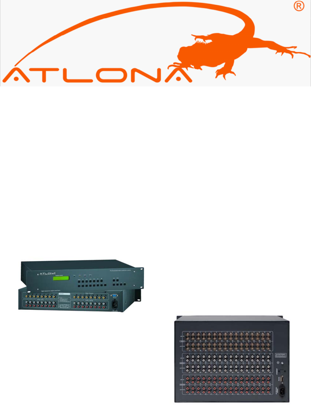
3.0 Connector Types The AV matrix swticher uses 2 types of Video Connectors for 4 Channel and 8 Channel RCA terminals are used. For 16 Channel, 24 Channel, 32 Channel, 48 Channel, 64 Channel, 96 Channel, 128 Channel BNC female terminals are use. Audio signal I/O terminals make up of 2 Channel, 4 Channel, 8 Channel, 16 Channel, 24 Channel, 32 Channel, 48 Channel, 64 Channel, 96 Channel 128 Channel with 3.8mm captive screw connectors(or RCA terminals).
3.1 Connecting the AV Switcher The VGA matrix switchers may take laptops, DVD players, video tape recorders, camcorders, cable TV and video their input signal source. Projectors, RP TVs, displayers and amplifiers can be connected on the output signal . Atlona Technologies www.atlona.
3.2 Audio signal connection: “AUDIO INPUTS”, “AUDIO OUTPUTS” audio network interface in RGB matrix switchers can be connected to the audio signal and amplify sources. Audio connection is little more complicated than video. It has two types of connection: balanced and unbalanced. The balanced connection transmits a pair of balanced signals with two cables. Because Interferences will have the same intensity and the opposite phases on the two cables; it will be counteracted in the end.
Example: To transfer input channel No.3 to output channel No.1 Operation: Press buttons in this order : “3” in IN PUT area, “1” in OUT PUT area. 4.1 Operation Controls for AV1616 “1,2,3,4” Keypad: Keys to select I/O channels and save/recall preset commands “AV” AV Synchronal button: To transfer video and audio signal synchronously by the switcher Example: To transfer both the video and the audio signals from input channel No.3 to output channel No.6.
Example1: To transfer video and audio signals from input channel No.7 to all output channels Operation: Press buttons in this order “7”, “ALL” Note: This command need not follow by “END” & “ENTER” Example2: To transfer all input signals to the corresponding output channels respectively. In another word, to switch to this status: 1->1, 2->2, 3->3, 4->4……16->16.
4.2 Additional Controls for AV32, AV48, AV64, AV96, AV128 “UNDO” Undo button: To resume to the status before the command just performed “PROGRAM” Group programming button: To define, recall and clear a group of output channel Example1: To group the output channels No.1,2,3,4,5 under the Group1 Operation: Press buttons in this order “1”, “Program”, “Program”, “1”, “2”, “3”, “4”, “5” Example2: To transfer signals from input channel No.
Display feedback on LCD: The video signal of output channel No.4 is transferred from the input channel No.3 and the audio signal is from the input channel No.2 Atlona Technologies www.atlona.
4.3 Remote Control Operation The Matrix can be controlled with the infrared remote control. The function buttons on the remote are the same as the ones on the front control panel, the remote uses the same commands and in the same order you would input them. 5.0 Operation of Application Software Switcher 2.0 is a switcher control application compatible with switchers with different inputs and outputs.
According to practical needs, user can select and operate at different function tabs such as SYSTEM, AUTO, KEYBOARD, CUSTOM CODE, CODE GROUP and SEND/RECEIVE CODE LIST. On the right hand side of the main window, there are 256 buttons representing for the 256 output channels.
5.1 Keyboard Tab Because the function buttons on this tab are the same with the ones on the front control panel, it shares the same control operation and command format with the control panel. Please refer the details in Chapter 7 Operation of the Control Panel 5.2 Auto Tab This tab is used to test the switcher after connecting it to all the input and outputs device. For example, to test the function of an RGB64X32 matrix switcher, the Auto Tab is set as below after finishing all the connection.
5.3 Custom Code Tab Select between ASCII and HEX format command codes ( for command details, please refer to section) Help: Displays the list of commans codes. Send: Sends out the typed commans codes. For example, to transfer the video and audio signals from the input channel No.1 to the output channel No.7, and the audio signals from the input channel No.2 to the output channel No.4, just perform the following steps below. 1. Select the “ASCII” as the command codes format; 2.
5.4 Code Group Tab New: Creat new a group of preset commands Open: Opens a group of preset commands Save: Saves the present group of preset commands Execute: Executse a selected preset command or a selected group of preset commands Clear: Clears the feedback window Add Code ltem: To add another new group of preset commands Edit: To edit the User’s name (User), Delete: Deletes the selected group. Atlona Technologies www.atlona.
5.5 Send / Recieve Code List Tab Send List window: Lists sent command code Received List window: Lists feedback from the switcher Clear: Clears either of the two lists 6.0 RS-232 Operation With the application “Switcher 2.00” one is able to control and operate the RGB Matrix remotely Communication protocol: Baud rate: 9600 Data bit: 8 Stop bit: 1 Parity bit: none Atlona Technologies www.atlona.
Command Types System Command Command Codes Functions /*Type; /+xxxxxxxx; Acquires the models information. Rewrites the passwords: must be 8 digits. /%Lock; /%Unlock; Locks the keyboard. Unlocks the keyboard. /:BellOff; /:BellOn; /^Version; /~CREATOR20; [x1]All Turn off the buzzer. Turn on the buzzer. Acquires the version of software Switch to CREATOR2.0 command system.
Command Types Command Codes [X1]*[X2]$ Functions Transfer audio signals from input channel [x1] to output channel [x2]. Transfer video signals from input channel [x1] to output channel [x2]. Transfer video signals from input channel [x1] to output channel [x2]. [X1]*[X2]% [X1]*[X2]& 7.
Series AV0404 AV8 Specifications Series Output Video Connector RCA Maximum/ Minimum level Impedance Echo Loss DC Offset Transition Type Sync Signal Input RCA Connector Output RCA Connector Gain 0dB Frequency Response General Harmonic Distortion + Noise S/N Segregation Rate Y/C Interferer CMRR Signal Impedance Maximum Input level Gain Error Max Output Level Control Type Serial Control Port Baud Rate and Protocol Serial Control Poling Protocol AV16 Series AV24 Series AV32 Series AV48, 64 AV96, 128 Series
Series AV0404 Specifications Connector Ethernet Protocol Speed Control Application Features Power Supply Temperature Humidity Size Weight MTBF Quality Guarantee AV8 AV16 AV24 AV32 Series Series Series Series RJ-45 Female(Optional accessory) TCP/IP AV48, 64 Series AV96, 128 Series Full/half-duplex 10/100 Switch 2.
8.0 Troubleshooting Problem Output image is displayed with a ghost Solution Check display settings, try another high quality cable Color loss or no video on output signal Check both the input and output connections Remote control doesnt work Check batteries, If borken, contact dealer The switcher cannot be controlled by computer Check the COM pot in the software. through COM port. Make sure the COM is working NO sound when switching with I/O signal. Make sure the beeper is switched on.