
User Manual


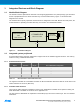


Table Of Contents

ATSAMR21B18-MZ210PA [PRELIMINARY DATASHEET]
Atmel-42486C-ATSAMR21B18-MZ210PA_Datasheet_03/2016
6
6
2.3 Footprint Recommendation
Since the antenna is integrated, a number of design constraints have to be considered for the base board design.
2.3.1 Pin header mounting
The module can be mounted on pin headers with 2mm pitch like the SAMTEC TMM series. This mounting
scheme requires a 7-pin single row header and two single pins next to the antenna. The pins are supposed to be
assembled on the base board in the normal top assembly process.
It is required to mount the module at the outline of the base board and to orient the antenna towards the board
edge. See Figure 2-2 for the placement range in relation to the base board edge. The area underneath the
antenna shall not be filled with copper.
The area underneath the module plus a margin of additional six millimeters shall be filled with copper on the base
board and tied to the ground plane with additional vias.
Figure 2-2. Through hole footprint drawing
Best way is to install the module with the antenna area to protrude beyond the board edge. If the system design
does not allow the antenna area to stand out, the module can be positioned in line with the board edge. Installing
the module further inside may cause a degradation in performance.
The mounting distance in between the module and the base board shall be in between 1mm and 2mm. For lower
distances the design rules for the SMT mounting according to Figure 2-3 will apply.