
User Manual


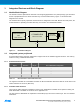


Table Of Contents

ATSAMR21B18-MZ210PA [PRELIMINARY DATASHEET]
Atmel-42486C-ATSAMR21B18-MZ210PA_Datasheet_03/2016
7
7
2.3.2 Surface solder mounting
For lowest cost, the module can be surface mounted to the base board. This saves the costs for the pin header.
The drawing in Figure 2-3 shows the recommended base board foot print.
The antenna shall not be influenced by the base board material. Any metal or dielectric material as FR-4 or
similar would tune the antenna out of band. The module has to be mounted with the antenna end to protrude
beyond the board edge. The area underneath the module shall be filled with a grounded copper fill.
As an alternative, the base board can be cut out as shown in Figure 2-3. This solution can help to keep the base
board outline by avoiding an antenna frequency deviation.
The SMT pads in the base board shall exceed the module outline at least by 0.45mm to achieve a controlled
solder result.
Figure 2-3. Base board design for SMT module mounting