
User's Manual


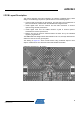

Table Of Contents

10
AVR2043
8345A-AVR-11/10
5.1 PCB detail 1 – balanced RF pin fan out
Figure 5-2. Board layout – RF pin fan out.
The Atmel AT86RF231 antenna port should be connected to a 100 load with a small
series inductance of 1nH to 2nH. This is achieved with the connection fan out in
between the IC pins and the DC blocking capacitors, C26 and C27. The trace width is
kept small at 0.2mm for a length of approximately 1.5mm. The REB231ED is a two-
layer FR4 board with a thickness of 1.5mm. Therefore, the distributed capacitance
between top and bottom is low, and transmission lines are rather inductive.