
User's Manual


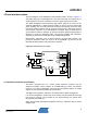
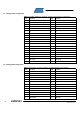

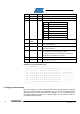


Table Of Contents

6
AVR2043
8345A-AVR-11/10
Address Name Type Description
0x10 Board family uint8 Internal board family identifier
0x11 Revision uint8[3] Board revision number ##.##.##
0x14 Feature uint8 Board features, coded into seven bits
7 Reserved
6 Reserved
5 External LNA
4 External PA
3 Reserved
2 Diversity
1 Antenna
0 SMA connector
0x15
Cal OSC
16MHz
uint8 RF231 XTAL calibration value, register XTAL_TRIM
0x16 Cal RC 3.6V uint8
Atmel ATmega1281 internal RC oscillator calibration value @
3.6V, register OSCCAL
0x17 Cal RC 2.0V uint8
Atmel ATmega1281 internal RC oscillator calibration value @
2.0V, register OSCCAL
0x18 Antenna gain Int8
Antenna gain [resolution 1/10dBi].
For example, 15 will indicate a gain of 1.5dBi.
The values 00h and FFh are per definition invalid. Zero or
-0.1dBi has to be indicated as 01h or FEh
0x20 Board name char[30] Textual board description
0x3E CRC uint16
16-bit CRC checksum, standard ITU-T generator polynomial
G
16
(x) = x
16
+ x
12
+ x
5
+ 1
Figure 4-3. Example EEPROM dump.
-----| EEPROM dump |--------------
0000 - 49 41 17 FF FF 25 04 00 D6 11 00 00 2A 00 00 00 IA...%......*...
0010 - 02 04 01 01 06 02 A8 A9 01 FF FF FF FF FF FF FF ................
0020 - 52 61 64 69 6F 45 78 74 65 6E 64 65 72 32 33 31 RadioExtender231
0030 - 45 44 00 00 00 00 00 00 00 00 00 00 00 00 8D 9B ED..............
0040 - FF FF FF FF FF FF FF FF FF FF FF FF FF FF FF FF ................
0050 - FF FF FF FF FF FF FF FF FF FF FF FF FF FF FF FF ................
0060 - FF FF FF FF FF FF FF FF FF FF FF FF FF FF FF FF ................
0070 - FF FF FF FF FF FF FF FF FF FF FF FF FF FF FF FF ................
----------------------------------
4.3 Supply current sensing
The power supply pins of the radio transceiver are protected against overvoltage
stress and reverse polarity at the EXPAND1 pins (net CVTG, net DGND) using a
Zener diode (D1) and a thermal fuse (F1) (see Exhibit A.1). This is re
quired because
the Atmel STK500 will provide 5V as default voltage, and the board can also be
mounted with reverse polarity.