
User's Manual


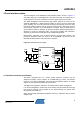


Table Of Contents

8
AVR2043
8345A-AVR-11/10
redesign of R8 and C36. In case of RC cut-off frequency adjustments, depending on
the specific load and signal routing conditions, one may observe performance
degradation of channel 26.
NOTE Channel 26 (2480MHz) is affected by the following harmonics: 155 x 16MHz or 310 x
8MHz.
By default, CLKM is routed to a microcontroller timer input; check the individual
configuration resistors in the schematic drawing. To connect CLKM to the
microcontroller main clock input, assemble R3 with a 0 resistor.
4.5 RF section
The Atmel AT86RF231 radio transceiver incorporates all RF and BB critical
components necessary to transmit and receive signals according to IEEE 802.15.4 or
proprietary ISM data rates.
A balun, B1, performs the differential to single-ended conversion of the RF signal to
connect the Atmel AT86RF231 to the RF switch, U1. The RF switch is controlled by
the radio transceiver output, DIG1, and selects one of the two antennas. The signal is
routed to the ceramic antenna, passing a tuning line. Solder pads located along the
tuning line allow for the optimization of antenna matching without the need for
redesigning the REB. Detailed information about the antenna diversity feature is given
in [1] and [3].
Optionally,
one or two SMA connectors can be assembled if conducted
measurements are to be performed. Refer to the schematic and populate coupling
capacitors C11/C12 and C18/C19 accordingly.