
User's Manual
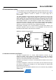

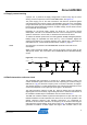
Table Of Contents

Atmel AVR2080
5
8479A-AVR-01/12
Pin# Function Pin# Function
29 PB1 (MCLK) 30 PB0 (open)
31 PD7 (SLPTR) 32 PD6 (DIG2)
33 PD5 (TP2) 34 PD4 (open)
35 PD3 (TP3) 36 PD2 (IRQ)
37 PD1 (TP4) 38 PD0 (open)
39 GND 40 EE#WP (write protect EEPROM)
4.2 ID EEPROM
To identify the board type by software, an optional identification (ID) EEPROM is
populated. Information about the board, the node MAC address and production
calibration values are stored here. An Atmel AT25010B [8] with 128
× 8-bit
organization and SPI bus is used because of its small package and low-voltage / low-
power operation.
The SPI bus is shared between the EEPROM and the transceiver. The select signal
for each SPI slave (EEPROM, radio transceiver) is decoded with the reset line of the
transceiver, RSTN. Therefore, the EEPROM is addressed when the radio transceiver
is held in reset (RSTN = 0) (see Figure 4-2).
Figure 4-2. EEPROM ac
cess decoding logic (Atmel ATmega1281 configuration).
>1
>1
PB5 (RSTN)
SEL#
RSTN
SPIPB1..3 (SPI)
Transceiver
AT86RF231
On-Board
EEPROM
PB0 (SEL)
/RST
/SEL
#CS
The EEPROM data are written during board production testing. A unique serial
number, the MAC address
1
, and calibration values are stored. These can be used to
optimize system performance.
NOTE Final products do not require this external ID EEPROM. All data can be stored directly
within the microcontroller’s internal EEPROM.
1
Note: MAC addresses used for this package are Atmel property. The use of these
MAC addresses for development purposes is permitted.