
User's Manual
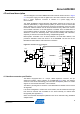
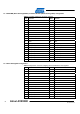
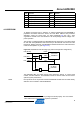
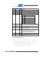
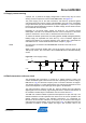
Table Of Contents

6
Atmel AVR2080
8479A-AVR-01/12
Figure 4-3 shows a detailed description of the EEPROM data structure.
Table 4-3. ID EEPROM mapping.
Address Name Type Description
0x00 MAC address uint64 MAC address for the 802.15.4 node, little endian byte order
0x08 Serial number uint64 Board serial number, little endian byte order
0x10 Board family uint8 Internal board family identifier
0x11 Revision uint8[3] Board revision number ##.##.##
0x14 Feature uint8 Board features, coded into seven bits
7 Reserved
6 Reserved
5 External LNA
4 External PA
3 Reserved
2 Diversity
1 Antenna
0 SMA connector
0x15
Cal OSC
16MHz
uint8 RF231 XTAL calibration value, register XTAL_TRIM
0x16 Cal RC 3.6V uint8
Atmel ATmega1281 internal RC oscillator calibration value
@ 3.6V, register OSCCAL
0x17 Cal RC 2.0V uint8
Atmel ATmega1281 internal RC oscillator calibration value
@ 2.0V, register OSCCAL
0x18 Antenna gain Int8
Antenna gain [resolution 1/10dBi].
For example, 15 will indicate a gain of 1.5dBi.
The values 00h and FFh are per definition invalid. Zero or
-0.1dBi has to be indicated as 01h or FEh
0x20 Board name char[30] Textual board description
0x3E CRC uint16
16-bit CRC checksum, standard ITU-T generator
polynomial G
16
(x) = x
16
+ x
12
+ x
5
+ 1
Figure 4-3. Example EEPROM dump.
-----| EEPROM dump |--------------
0000 - 49 41 17 FF FF 25 04 00 D6 11 00 00 2A 00 00 00 IA...%......*...
0010 - 02 04 01 01 06 02 A8 A9 01 FF FF FF FF FF FF FF ................
0020 - 52 61 64 69 6F 45 78 74 65 6E 64 65 72 32 33 31 RadioExtender231
0030 - 46 45 32 00 00 00 00 00 00 00 00 00 00 00 8D 9B FE2.............
0040 - FF FF FF FF FF FF FF FF FF FF FF FF FF FF FF FF ................
0050 - FF FF FF FF FF FF FF FF FF FF FF FF FF FF FF FF ................
0060 - FF FF FF FF FF FF FF FF FF FF FF FF FF FF FF FF ................
0070 - FF FF FF FF FF FF FF FF FF FF FF FF FF FF FF FF ................
----------------------------------