
User's Manual
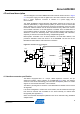
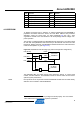
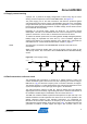
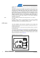
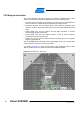
Table Of Contents

Atmel AVR2080
9
8479A-AVR-01/12
In transmit mode, nominal antenna port transmit output power is +20dBm for Atmel
AT86RF231 sub-register setting TX_PWR = 0x0A at EVDD = 3.0V nominal supply
voltage. Second and third harmonics levels are less than -42dBm/MHz. Transmit
output power level is adjusted using the AT86RF231 TX output power, controlled via
register bits TX_PWR.
The supply voltage can be increased to 3.6V to further increase transmit output
power. There is provision on the PCB for C-L-C low pass filtering at the antenna ports
to reduce harmonic levels at these higher output powers.
In receive mode, conducted sensitivity is better than -104dBm for 1% packet error
rate. The SE2431L has a typical receive noise figure of 2dB which includes all RF
switch input losses.
Referring to the Atmel REB231FE2 schematic in Appendix A.1, the RF interfac
e
consists of two antenna ports. By default two on-board ceramic antennas are
connected allowing radiated measurements. Solder pads located along the tuning line
allow for the optimization of antenna matching without the need for redesigning the
PCB. Detailed information about the antenna diversity feature are given in [1] and [3].
Optionally two swit
ched in-line MS-147 RF connectors, which disconnect the on-
board antennas, allow conducted measurements. The SE2431L antenna ports are
controlled by AT86RF231 pin DIG1 connected to SE2431L pin ANT_SEL.
The SE2431L operating mode is determined by control lines CTX, CPS and CSD.
The default configuration connects CPS pin to EVDD via R31. This means that in
receive mode the LNA will always be enabled for maximum sensitivity. Enabling low
power RX bypass mode requires removing R31 and R32 populated with 0R resistor.
The PA is enabled when CTX is high and the LNA is enabled when CTX is low. When
CSD pin is low, the SE2431L goes into low current standby mode (<1 µA current
consumption), irrespective of the state of CTX and CPS. CSD is connected to the
AT86RF231 analog LDO regulator output (AVDD). AVDD is 1.8V for all AT86RF231
states except P_ON, SLEEP, RESET, and TRX_OFF. To enable/disable the
SE2431L immediately and independently from individual radio transceiver states, an
additional GPIO control line from the microcontroller is required.
The SE2431L has two analog power supply pins, VCC1 and VCC2, which power the
internal analog circuitry. This supply is connected to the REB231FE2 EVDD supply
voltage.
The interface between the AT86RF231 and the Skyworks SE2431L is single-ended
50, optimized for high performance and low cost applications. The unused
AT86RF231 RFN pin is terminated to ground with a 50 resistor and DC block.
Avoiding a balun helps minimizing the bill of materials cost. In transmit mode, the
AT86RF231 transmit output power needs to be set higher compared to a differential
TRX-FEM interface using a balun. In receive mode, the effective gain ahead of the
AT86RF231 is 3dB less than the specified SE2431L LNA gain (12.5dB). The resulting
loss in sensitivity is about 0.3…0.4dB.