AVR2044: RCB128RFA1 Hardware User Manual Features • Stand alone operable Radio Controller Board (RCB) • The design is based on the single chip ATmega128RFA1 to support IEEE 802.15.
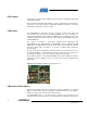
Disclaimer Typical values contained in this application note are based on simulations and testing of individual examples. Any information about third party materials or parts is included into this document for convenience. The vendor may have changed the information in between. Check the individual part information for latest changes. 3 Overview The RCB128RFA1 is designed to provide a reference design for the single chip microcontroller and radio transceiver ATmega128RFA1 [1].
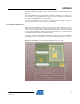
AVR2044 antenna, mounted at the SMA connector, the board will act as a ground plane for this antenna. This design with RF shield is implementing one M2.5 mounting hole (see Figure 4-1). In consequence, one mounting bolt has to be removed on several base boards types to mount the RCB128RFA1 in a correct position. The other mounting hole is reserved for a battery holder. If battery operation is required, base boards should not make use of this mount. 4.1.
.1.2 Interface Connector Specification Figure 4-2. RCB128RFA1 – Interface Connector Drawing The base board interface connector EXT0/1, mounted on the RCB, is a 30 pin, 50 mil type from SAMTEC. The detailed part number is: SFM-115-L2-S-D-LC. L2 is the low insertion force (LIF) variant to allow easy mounting. The drawing shown in Figure 4-2 is a copy taken from a SAMTEC datasheet. Check the latest datasheet for possible updates and changes.
AVR2044 4.1.3 Application (Base) Board Connectors Figure 4-3. Application Board Connector Drawing The drawing in Figure 4-3 shows the connector to be used on a base board to interface the RCB EXT0/1 connectors. The detailed SAMTEC part number is: TFM-115-02-S-D. Alternatively a Tyco part can be used: Tyco 5-104655-4 Note: The Tyco part requires a different footprint design! The drawing shown in Figure 4-3 is a copy taken from a SAMTEC datasheet.
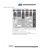
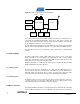
Figure 5-1. Radio Controller Board - Block Diagram 32 kHz 16 MHz Expansion Connector 1 ATmega128RFA1 Balun Expansion Connector 2 Pushbutton LEDs ID EEPROM The radio transceiver incorporates MAC hardware accelerators to handle all actions concerning RF modulation/demodulation, signal processing, frame reception and transmission. Further information about the radio transceiver and the microcontroller are provided in the datasheet, see reference [1].
AVR2044 16 kB of internal SRAM, supported by a rich set of peripheral units, makes it suitable for a full function sensor network node. The microcontroller is capable of operating as a PAN-coordinator, a full function device (FFD) as well as a reduced function device (RFD), as defined by IEEE802.15.4 [2]. However, the RCB is not limited to this and can be programmed to operate in other standards or ISM applications, too. All spare I/O pins are accessible via the expansion connectors for external use.
• 16 MHz calibrated internal RC oscillator • 128 kHz internal RC oscillator • 16 MHz radio reference crystal The calibrated internal RC oscillator, prescaled to 8 MHz is used as the default clocking. It is recommended to use the MAC symbol counter, see [1], clocked from the 16 MHz radio crystal, as a reference to calibrate the RC oscillator for higher accuracy. The symbol counter replaces and enhances the CLKM driven timer1 function, originally available in ATmega1281V based solutions.
AVR2044 organization and SPI interface is used because of its small package, low voltage and low power operation. Compared to Atmega1281V based RCB’s, the ID-EEPROM interface has been designed in a different way. Accessing the ID-EEPROM requires PG5 set to logic low. This pin is not used on Atmega1281V based RCB’s, refer to Figure 5-3 for details. Figure 5-3.
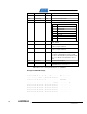
Address Name Type Description 0x08 Serial Number uint64 Board serial number, little endian byte order 0x10 Board Family uint8 Internal board family identifier 0x11 Revision uint8 Board revision number eg. 06 03 01 0x14 Feature uint8 Board features, coded into 7 Bits 7 Reserved 6 Reserved 5 External LNA 4 External PA 3 Reserved 2 Diversity 1 Antenna 0 SMA connector 0x15 Cal OSC 16 MHz uint8 RF231 XTAL calibration value, register “XTAL_TRIM” 0x16 Cal RC 3.
AVR2044 5.6 External Peripherals The RCB is equipped with two 50 mil connectors (EXT0/1) to mount the RCB on a variety of expansion boards (base boards). The connectors providing access to all spare Atmega128RFA1 pins, including USART, TWI, ADC and PWM. Make sure that any RCB base board that is used together with the RCB128RFA1 will not drive the TST signal (EXT1, pin5) high during operation. The only occasion to drive the TST signal high is during parallel programming.
EXT1 Pin# RCB128RFA1 Function 1281V RCB Function Pin# RCB128RFA1 Function 1281V RCB Function 1 PB1 PB1 (SCK) 2 GND GND 3 PE7 PE7 4 PE6 PE6 5 TST (connect for parallel programming only) PE5 6 RSTON PE4 7 PE3 PE3 8 PE2 PE2 9 PE1 PE1 (PDO) 10 PE0 PE0 (PDI) 11 GND AGND 12 AREF AREF 13 PF0 PF0 14 PF1 PF1 15 PF2 PF2 16 PF3 PF3 17 PF4 PF4 (TCK) 18 PF5 PF5 (TMS) 19 PF6 PF6 (TDO) 20 PF7 PF7 (TDI) 21 V_RCB V_RCB 22 GND GND 23 PB0 PA0 24 PB1
AVR2044 2 Figure 5-4.
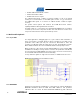
Figure 5-5. RCB128RFA1 Bottom Layer Design Details 5.7.1 PCB Detail 1 – Balanced RF Fan Out The radio transceiver RF ports require a small serial inductance in series with the balun or antenna pins. A reasonable inductance value is 1…2 nH. With the given 1.5 mm RF4 substrate, it is not possible to design a differential 100 Ohm transmission line. Thus, traces between filter-balun and single chip are kept at a reasonable small width of 0.2mm.
AVR2044 5.7.3 PCB Detail 3 – Bias DC Block, AC Ground The RCB uses an integrated filter-balun, refer to [6]. The component provides pin 2 as a bias port towards the differential pins. To avoid a DC connection of the radio transceiver circuitry, refer to [1], filter balun pin2 requires a DC blocking capacitor C1 to create an AC GND connection only. This capacitor is to be placed as close as possible to the filter-balun to ensure a low impedance AC connection.
Any crosstalk from digital lines into the crystal signals increases the phase noise, and reduces the radio transceiver performance. A grounded guard trace is placed around the crystal area to protect the crystal against digital noise. To investigate the impact of digital noise on the reference crystal, it’s recommended to perform packet error rate tests with potential digital noise sources enabled and disabled.
AVR2044 7 Electrical Characteristics 7.1 Absolute Maximum Ratings Stresses beyond those listed under “Absolute Maximum Ratings” may cause permanent damage to the RCB. This is a stress rating only and functional operation of the device at these or any other conditions beyond those indicated in the operational sections of this manual are not implied. Exposure to absolute maximum rating conditions for extended periods may affect device reliability.
7.4 Current Consumption Specifications Power consumption figures of the individual Atmega128RFA1 building blocks and operation conditions are listed in the datasheet [1]. To determine the RCB current consumption the following values are to be taken into account: Test Conditions (unless otherwise stated) 1,2 : VDD = 3.0V, TOP = 25°C No. Symbol Parameter Condition 7.4.1 ILED Current per LED when driving port pin is low 7.4.2 IEE_SLEEP ID-EEPROM standby current LED on current Note: Min. Typ.
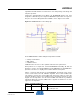
AVR2044 8 Appendix A – Board Design Information A.1 – Schematic Figure 8-1.
Figure 8-2. RCB128RFA1 – SOC Section 1 Note: Please be aware of the TST and CLKI signal routing on RCB128RFA1. The Connector mapping is visible in Figure 8-4 as well as pull down resistors (R8, R9) for both signals. For normal operation the TST signal must be pulled to ground all the time. The only occasion to drive the TST signal high is during parallel programming. Please refer to [1] for detailed information.
AVR2044 Figure 8-3.
Figure 8-4.
AVR2044 A.2 – Assembly Drawing Figure 8-5.
A.3 – Bill of Material (BoM) Table 8-1 Bill of Material Designator Description B1 Quantity Manufacturer P/N Balun+Filter_SMD 1 Johanson 2450FB15L0001 E AAAx2 1 COMF BH-421-3 Batt1 Battery C1, C3, C5 Capacitor 22p 3 generic 0402 C2 Capacitor 10n 1 generic 0402 C4, C7 Capacitor 1uF 2 generic 0603 C6, C10 Capacitor 10p 2 generic 0402 C8, C9, C11, C12, C13, C14, C15, C18, C19 Capacitor 100n 9 generic 0402 C16 Electrolytic Capacitor 47uF/6V 1 D1 Schottky Diode n.i.
AVR2044 A.4 – Radio Certification The RCB128RFA1 has received regulatory approvals for modular devices in the United States, European countries and Japan. A.4.1 United States (FCC) Compliance Statement (Part 15.19) The device complies with Part 15 of the FCC rules.
Compliance Statement (Part 15.105(b)) This equipment has been tested and found to comply with the limits for a Class B digital device, pursuant to Part 15 of the FCC Rules. These limits are designed to provide reasonable protection against harmful interference in a residential installation. This equipment generates uses and can radiate radio frequency energy and, if not installed and used in accordance with the instructions, may cause harmful interference to radio communications.
AVR2044 A.4.3 Approved Antenna The device has been tested and approved for use with the antenna listed below. The device may be integrated with other custom design antennas which OEM installer must authorize with respective regulatory agencies. The used antenna is connected to the radio module via an SMA connection.
Appendix B – EVALUATION BOARD/KIT IMPORTANT NOTICE This evaluation board/kit is intended for use for FURTHER ENGINEERING, DEVELOPMENT, DEMONSTRATION, OR EVALUATION PURPOSES ONLY. It is not a finished product and may not (yet) comply with some or any technical or legal requirements that are applicable to finished products, including, without limitation, directives regarding electromagnetic compatibility, recycling (WEEE), FCC, CE or UL (except as may be otherwise noted on the board/kit).
AVR2044 References [1] AVR2044; 8-bit AVR Microcontroller with Low Power 2.4 GHz Transceiver for ZigBee, IEEE 802.15.4, 6LoWPAN, RF4CE, SP100, WirelessHART and ISM Applications; Preliminary Datasheet; Rev. 8266AB-MCU Wireless-12/09; Atmel Corporation [2] IEEE Std 802.15.4™-2006: Wireless Medium Access Control (MAC) and Physical Layer (PHY) Specifications for Low-Rate Wireless Personal Area Networks (LR-WPANs) [3] FCC Code of Federal Register (CFR); Part 47; Section 15.35, Section 15.205, Section 15.
Table of Contents Features ............................................................................................... 1 1 Introduction ...................................................................................... 1 2 Disclaimer......................................................................................... 2 3 Overview ........................................................................................... 2 4 Mechanical Description .................................................
Disclaimer Headquarters International Atmel Corporation 2325 Orchard Parkway San Jose, CA 95131 USA Tel: 1(408) 441-0311 Fax: 1(408) 487-2600 Atmel Asia Unit 1-5 & 16, 19/F BEA Tower, Millennium City 5 418 Kwun Tong Road Kwun Tong, Kowloon Hong Kong Tel: (852) 2245-6100 Fax: (852) 2722-1369 Atmel Europe Le Krebs 8, Rue Jean-Pierre Timbaud BP 309 78054 Saint-Quentin-enYvelines Cedex France Tel: (33) 1-30-60-70-00 Fax: (33) 1-30-60-71-11 Atmel Japan 9F, Tonetsu Shinkawa Bldg.