
User's Manual


2
AVR2044
8339A-AVR-09/10
2 Disclaimer
Typical values contained in this application note are based on simulations and testing
of individual examples.
Any information about third party materials or parts is included into this document for
convenience. The vendor may have changed the information in between. Check the
individual part information for latest changes.
3 Overview
The RCB128RFA1 is designed to provide a reference design for the single chip
microcontroller and radio transceiver ATmega128RFA1 [1]. The IC integrates a
powerful 8-bit AVR RISC microcontroller, an IEEE802.15.4-compliant transceiver and
additional periphery. The built-in radio transceiver supports the worldwide accessible
2.4 GHz ISM band.
The system is designed to demonstrate standard based applications like
ZigBee/IEEE 802.15.4, ZigBee RF4CE, and 6LoWPAN as well as high data rate ISM
applications. The SMA antenna connector allows either operation with the antenna
provided together with the RCB or to perform conducted RF performance
measurements.
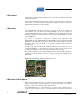
The RF section has been shielded to eliminate interference from external sources to
the ATmega128RFA1. To investigate the reference design area, the shield can be
opened by removing the snap-in cover while the RCB is not in operation.
Most peripheral features of the ATmega128RFA1 where made available through two
expansion connectors (EXT0/1). There is a variety of base boards available for the
RCB family.
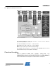
Figure 3-1. RCB128RFA1 with Removed Snap-In Cover
4 Mechanical Description
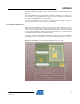
RCB’s, demonstrating radio transceiver and microcontroller capabilities, are equipped
with two 50 mil, 30 pin connectors (ETX0/1), separated 22 mm from each other to
interface to various port extension boards (base boards).
The RCB128RFA1 has no on-board antenna, so that a board separation into an
electronic and an antenna section is not required. When used with a quarter wave