
User's Manual


6
AVR2044
8339A-AVR-09/10
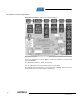
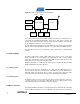
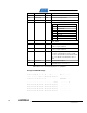
Figure 5-1. Radio Controller Board - Block Diagram
The radio transceiver incorporates MAC hardware accelerators to handle all actions
concerning RF modulation/demodulation, signal processing, frame reception and
transmission. Further information about the radio transceiver and the microcontroller
are provided in the datasheet, see reference [1].
The RF front-end implementation was kept minimal by using a balun with integrated
filter. An antenna, provided with the RCB, has to be connected to the SMA connector.
All components are placed on one PCB side to demonstrate a low cost manufacturing
solution.
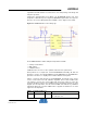
5.1 Power Supply
The RCB is powered by a single supply voltage in the range of 1.8 V – 3.6 V, which
makes it possible to use 1.5 V alkaline cells. Optionally, the power can be supplied
from a base board. In this case the power switch SW1 must be in OFF position or the
battery has to be removed from the battery holder.
All PCB components are supplied by this single supply to minimize the bill of material
(BoM) and maximize the power efficiency.
5.1.1 Battery power
For autonomous operation, the RCB can be supplied by two AAA batteries to be
inserted in the battery clip on the back side of the RCB. Use power switch SW1 to
manually switch on/off the board. Note, a power cycle may not be detected if radio
transceiver and microcontroller are in sleep mode, and all periphery disabled.
5.1.2 External power
An RCB mounted on a base board may be powered via the expansion connectors,
see Table 5-2. In this case the power switch SW1 has to be in OFF position to avoid
unintentionally charging of the batteries, if they are applied.
5.2 Microcontroller
The ATmega128RFA1 integrates a low-power 8-bit microcontroller based on the AVR
enhanced RISC architecture. The non-volatile flash program memory of 128 kB and
32
kHz
16
MHz
ATmega128RFA1
Expansion
Connector
1
ID
EEPROM
LEDs
Pushbutton
Expansion
Connector
2
Balun