
User's Manual


8
AVR2044
8339A-AVR-09/10
• 16 MHz calibrated internal RC oscillator
• 128 kHz internal RC oscillator
• 16 MHz radio reference crystal
The calibrated internal RC oscillator, prescaled to 8 MHz is used as the default
clocking. It is recommended to use the MAC symbol counter, see [1], clocked from
the 16 MHz radio crystal, as a reference to calibrate the RC oscillator for higher
accuracy.
The symbol counter replaces and enhances the CLKM driven timer1 function,
originally available in ATmega1281V based solutions.
A 32 kHz crystal Q1 is connected to the related ATmega128RFA1 pins (17-TOSC2;
18-TOSC1) to be used as a low power real time clock. This time base can also run in
sleep mode and create timer based system wake-up events.
5.5 On-Board Peripherals
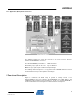
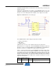
5.5.1 Key & LED’s
For simple applications, debugging purposes or just to deliver status information, a
basic user interface is provided directly on-board, consisting of four LED’s and a
pushbutton. Three LED’s (D2…D4) are connected to PE2…PE4 for active low
operation; one LED (D5) signals the single chip reset state. The pushbutton (T1) pulls
PE5 to GND, intended to be used in combination with the internal pull-up resistor.
When mounted on a base board, I/O ports PE4 and PE5 are used to emulate #WR
and #RD lines handling a memory interface. Therefore the pushbutton and LED D4
are not functional. On RCB128RFA1 the port G I/O lines can not be used since they
are shared with dedicated radio transceiver functionality.
In sleep, when the signals are supposed to be inactive, no additional current occurs.
Figure 5-2. RCB128RFA1 Key and LED Connection
5.5.2 ID-EEPROM
Firmware based board type identification is supported by an optional identification
EEPROM. Information about the RCB itself, MAC addresses and production
calibration data are stored. An Atmel AT25010A EEPROM [7] with 128x8 bit