
User's Manual

10
AVR600
8293-AVR-02/10
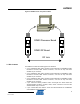
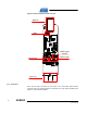
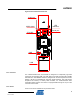
• 12 MHz: The crystal is required as input to the internal PLL of the AT32UC3A3256
to generate the base frequency for the full and high speed USB mode.
• 32 kHz: Used as input source for the real time clock.
Figure 4-4 Clock Locations
4.2.3 LEDs
Two LEDs are available connected to the AT32UC3A3256’s pins PX22 and PX41.
These are turned on by sinking current through the pin – logic low while acting as an
input.
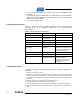
4.2.4 Headers
Four headers are available on the processor board:
• 10-pin header (J101): Interface for the radio frequency board.
• Three pin header RF (J102 – not mounted): Auxiliary signals that can be
patched in from the same three pin header on the radio frequency board. See
Table 4-2 for pinout.
• JTAG Interface (J103 – not mounted): Standard Atmel JTAG header.
• Three pin header UART (J105 – not mounted): See Table 4-3 for pinout.
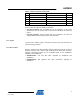
Table 4-2. J102 3-pin RF Auxiliary header
Pin Name
J102-1 Clock Output
J102-2 ID Chip
J102-3 Test pin – AT86RF230
Table 4-3. J105 3-pin UART header
Pin Name
J105-1 GND
J105-2 UART TX
J105-3 UART RX