
User's Manual

AVR600
7
8293-AVR-02/10
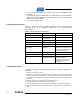
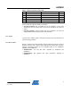
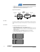
Table 4-1. Radio Frequency 10-pin header
Pin Name Name
Pin
1 Reset
Misc 2
3 Interrupt
Sleep Transmit 4
5 Chip Select
MOSI 6
7 MISO
SCK 8
9 GND
VCC (1.8 – 3.6V) 10
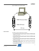
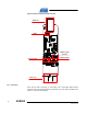
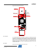
There are also two single row headers on the board:
• J103 (Not mounted): Two pin header that can be soldered in to do current
measurement with an ampere meter. R105 must be unsoldered to enable this
feature.
• J104 (Not mounted): Three pin header that can be soldered in to access the
auxiliary (Miscellaneous) signals from the radio transceiver.
4.1.2 Crystal
A high accuracy 16MHz crystal is mounted and used by the radio transceiver for
carrier frequency generation.
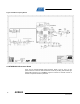
4.1.3 RF Front End
Since the output from the radio transceiver itself is a balanced signal pair, a balun is
needed to transform into a 50Ohm single ended signal fed to the SMA connector.
Johanson Technology provides two pin compatible baluns for the AT86RF230,
AT86RF231 and AT86RF212:
• 2450FB15L0001: 2.45 GHz filter balun optimized for AT86RF230 and
AT86RF231.
• 0896FB15A0100: Sub gigahertz filter balun combination optimized for
AT86RF212.