ZigBit™ 2.4 GHz Wireless Modules ....................................................................................................................
ZigBit™ 2.
Table of Contents Section 1 1.1 Summary............................................................................................................................ 1-1 1.2 Applications........................................................................................................................ 1-1 1.3 Key Features...................................................................................................................... 1-2 1.4 Benefits ............................................
Section 1 Introduction 1.1 Summary ZigBit™ is an ultra-compact, low-power, high-sensitivity 2.4 GHz IEEE 802.15.4/ZigBee® OEM module based on the innovative Atmel’s mixed-signal hardware platform. It is designed for wireless sensing, control and data acquisition applications. ZigBit modules eliminate the need for costly and time-consuming RF development, and shortens time to market for a wide range of wireless applications. Two different versions of 2.
Introduction 1.3 Key Features • Ultra compact size (24 x 13.5 x 2.0 mm for ATZB-24-A2 module and 18.8 x 13.5 x 2.
Introduction DTR Data Terminal Ready DIP Duap In-line package EEPROM Electrically Erasable Programmable Read-Only Memory ESD Electrostatic Discharge GPIO General Purpose Input/Output HAL Hardware Abstraction Layer HVAC Heating, Ventilating and Air Conditioning HW Hardware 2 IC Inter-Integrated Circuit IEEE Institute of Electrical and Electrionics Engineers IRQ Interrupt Request ISM Industrial, Scientific and Medical radio band JTAG Digital interface for debugging of embedded device
Introduction 1.6 Related Documents [1] Atmel 8-bit AVR Microcontroller with 64K/128K/256K Bytes In-System Programmable Flash. 2549F AVR 04/06 [2] Atmel Low-Power Transceiver for ZigBee Applications. AT86RF230 datasheet. doc5131.pdf [3] IEEE Std 802.15.4-2003 IEEE Standard for Information technology - Part 15.4 Wireless Medium Access Control (MAC) and Physical Layer (PHY) Specifications for Low-Rate Wireless Personal Area Networks (LR-WPANs) [4] ZigBee Specification.
Section 2 Zigbit™ Module Overview 2.1 Overview ZigBit is a low-power, high-sensitivity IEEE 802.15.4/ ZigBee-compliant OEM module. This multi-functional device occupies less than a square inch of space, which is comparable to a typical size of a single chip. Based on a solid combination of Atmel’s latest MCU Wireless hardware platform [1], the ZigBit offers superior radio performance, ultra-low power consumption, and exceptional ease of integration. Figure 2-1. ATZB-24-B0 Block Diagram VCC (1.8 - 3.
Zigbit™ Module Overview ZigBit modules comply with the FCC (Part 15), IC and ETSI (CE) rules applicable to the devices radiating in uncontrolled environment. For details, see “Agency Certifications” on page 4-22. ZigBit fully satisfies the requirements of the “Directive 2002/95/EC of the European Parliament and the Council of 27January 2003 on the restriction of the use of certain hazardous substances in electrical and electronic equipment” (RoHS).
Section 3 Specifications 3.1 Electrical Characteristics 3.1.1 Absolute Maximum Ratings Table 3-1. Absolute Maximum Ratings(1)(2) Parameters Min Max Voltage on any pin, except RESET with respect to Ground -0.5V VCC + 0.5V DC Current per I/O Pin 40 mA DC Current DVCC and DGND pins 200 mA Input RF Level +10 dBm Notes: 1. Absolute Maximum Ratings are the values beyond which damage to the device may occur. Under no circumstances must the absolute maximum ratings given in this table be violated.
Specifications Current consumption actually depends on multiple factors, including but not limited to, the board design and materials, BitCloud settings, network activity, EEPROM read/write operations. It also depends on MCU load and/or peripherals used by an application. 3.1.3 RF Characteristics Table 3-3. RF Characteristics Parameters Condition Frequency Band Unit 2.4000 to 2.
Specifications 3.2 Physical/Environmental Characteristics and Outline Parameters Value Comments 18.8 x 13.5 x 2.0 mm ATZB-24-B0 24.0 x 13.5 x 2.0 mm ATZB-24-A2 1.3g ATZB-24-B0 1.5g ATZB-24-A2 -20°C to +70°C -40°C to +85°C operational(1) Size Weight Operating Temperature Range Operating Relative Humidity Range Note: no more than 80% 1. Minor degration of clock stability may occur. Figure 3-1. ATZB-24-B0 Mechanical drawing ZigBit™ 2.
Specifications Figure 3-2. ATZB-24-A2 Mechanical drawing ZigBit™ 2.
Specifications 3.3 Pin Configuration Figure 3-3. ATZB-24-B0 Pinout Figure 3-4. ATZB-24-A2 Pinout ZigBit™ 2.
Specifications Table 3-6.
Specifications Table 3-6. Pin descriptions Default State after Power on Connector Pin Pin Name Description 35 AGND Analog ground 36 GPIO_1WR 1-wire interface(2)(3)(4)(7) I/O 37 UART_DTR DTR input (Data Terminal Ready) for UART.
Specifications 9. Using ferrite bead and 1 µF capacitor located closely to the power supply pin is recommended, as shown below. 10. Pins 44 through 48 are not designed for the ATZB-24-A2 module. Note these pins are used in ATZB-24-B0, see them in antenna schematics below. For ATZB-24-B0 combined with PCB Antenna For ATZB-24-B0 combined with External Antenna 11. In SPI mode, USART0_EXTCLK is output. In USART mode, this pin can be configured as either input or output pin. ZigBit™ 2.
Specifications 3.4 Mounting Information The below diagrams show the PCB layout recommended for ZigBit module. Neither via-holes nor wires are allowed on the PCB upper layer in area occupied by the module. As a critical requirement, RF_GND pins should be grounded via several holes to be located right next to the pins thus minimizing inductance and preventing both mismatch and losses. Figure 3-5. ATZB-24-B0 PCB Recommended Layout, Top View Figure 3-6.
Specifications 3.5 Sample Antenna Reference Designs This section presents PCB designs which combine ZigBit with different antennas: PCB onboard antenna, external antenna and dual chip antenna. These antenna reference designs are recommended for successful design-in. Figure 3-7. PCB Layout: Symmetric Dipole Antenna recommended for ATZB-24-B0 The symmetric dipole antenna above has been tuned for the particular design.
Specifications match, hence, affecting the pattern. The particular factors are the board material and thickness, shields, the material used for enclosure, the board neighborhood, and other components adjacent to antenna. 3.5.1 General recommendations Metal enclosure should not be used. Using low profile enclosure might also affect antenna tuning. Placing high profile components next to antenna should be avoided.
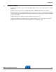
Specifications 3.6 Antenna specifications 3.6.1 ATZB-24-B0 Figure 3-8. Symmetric Dipole Antenna Pattern (horizontal and vertical plane) for ATZB-24-B0 ATZB-24-B0: ATZB-24-B0 ATZB-24-B0: ZigBit™ 2.
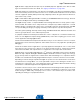
Specifications Figure 3-9. PCB Layout with 50 Ohm External Antenna recommended for ATZB-24-B0 In case the external unbalanced 50 Ohm antenna is required, it can be easily interfaced to ATZB-24-B0 module by using 2:1 balun as shown above. The reference design in Figure 3-10 demonstrates how to use SMA connector. Figure 3-10. SMA connectors ATZB-24-B0 ZigBit™ 2.
Specifications 3.6.2 ATZB-24-A2 Figure 3-11. Symmetric Dipole Antenna Pattern (horizontal and vertical plane) for ATZB-24-A2 ATZB-24-A2: ATZB-24-A2 ATZB-24-A2: Note: The antenna patterns presented above were observed using PCB enhanced with legs made of original nylon. ZigBit™ 2.
Specifications Figure 3-12. PCB Layout with Dual Chip Antenna Module recommended for ATZB-24-A2 Normally, chip antennas are more tolerant of the board or enclosure materials in ZigBit's neighborhood as well. However, general recommendations given above for the PCB antenna design still apply. The board design should prevent propagation of microwave field inside the board material.
Section 4 Agency Certifications 4.1 UNITED STATES (FCC) This equipment complies with Part 15 of the FCC rules and regulations. To fulfill FCC Certification requirements, an OEM manufacturer must comply with the following regulations: 1.
Agency Certifications Installers must be provided with antenna installation instructions and transmitter operating conditions for satisfying RF exposure compliance. This device is approved as a mobile device with respect to RF exposure compliance, and may only be marketed to OEM installers. Use in portable exposure conditions (FCC 2.1093) requires separate equipment authorization.
Agency Certifications 4.3 Approved Antenna List ATZB-24-A2 Module works with integrated dual chip antenna. The design of the antenna is fully compliant with all the aforementioned regulation. ATZB-24-B0 Module has been tested and approved for use with the antennas listed in the table below. ATZB-24-0B Module may be integrated with other custom design antennas which OEM installer must authorize with respective regulatory agencies. Table 4-1.
Section 5 Ordering Information 5.1 Ordering Information Part Number Description ATZB-24-B0R 2.4 GHz IEEE802.15.4/ZigBee OEM Module w/ Balanced RF Port ATZB-24-A2R 2.4 GHz IEEE802.15.4/ZigBee OEM Module with dual chip antenna Note: Tape&Reel quantity: 200 ZigBit™ 2.
Headquarters International Atmel Corporation 2325 Orchard Parkway San Jose, CA 95131 USA Tel: 1(408) 441-0311 Fax: 1(408) 487-2600 Atmel Asia Unit 1-5 & 16, 19/F BEA Tower, Millennium City 5 418 Kwun Tong Road Kwun Tong, Kowloon Hong Kong Tel: (852) 2245-6100 Fax: (852) 2722-1369 Atmel Europe Le Krebs 8, Rue Jean-Pierre Timbaud BP 309 78054 Saint-Quentin-enYvelines Cedex France Tel: (33) 1-30-60-70-00 Fax: (33) 1-30-60-71-11 Atmel Japan 9F, Tonetsu Shinkawa Bldg.