ZigBit™ 2.4 GHz Amplified Wireless Modules ...................................................................................................................
ZigBit™ 2.
Table of Contents Section 1 1.1 Summary............................................................................................................................ 1-1 1.2 Applications........................................................................................................................ 1-1 1.3 Key Features...................................................................................................................... 1-2 1.4 Benefits ............................................
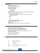
Section 1 Introduction 1.1 Summary ZigBit™ Am p is an ultra-comp act, extended ran ge, low-power, hig h-sensitivity 2.4GHz IEEE 802.15.4/ZigBee® OEM module from Atmel. Based on the innovative Atmel's mixed-signal hardware platform, this module is enhanced by an output power amplifier and an input low-noise amplifier, and is designed for wireless sensing, monitoring & control and data acquisition applications.
Introduction 1.3 Key Features • • • • • • • • • • • 1.4 Benefits • • • • • • • • • 1.5 Ultra compact size (38.0 x 13.5 x 2.
Introduction GPIO General Purpose Input/Output HAF High Frequency HVAC Heating, Ventilating and Air Conditioning HW Hardware 2 IC Inter-Integrated Circuit IEEE Institute of Electrical and Electrionics Engineers IRQ Interrupt Request ISM Industrial, Scientific and Medical radio band JTAG Digital interface for debugging of embedded device, also known as IEEE 1149.1 standard interface LNA Low Noise Amplifier MAC Medium Access Control layer MCU Microcontroller Unit.
Introduction 1.6 Related Documents [1] ZigBit™ 2.4 GHz Wireless Modules ATZB-24-B0/A2. Product datasheet. Atmel’s doc8226.pdf [2]. ZigBit™ 700/800/900 MHz Wireless Modules ATZB-900-B. Product datasheet. Atmel’s doc8227.pdf [3] ZigBit™ Development Kit. User's Guide. MeshNetics Doc. S-ZDK-451~01 [4] Atmel 8-bit AVR Microcontroller with 64K/128K/256K Bytes In-System Programmable Flash. 2549F AVR 04/06 [5] Atmel Low-Power Transceiver for ZigBee Applications. AT86RF230 datasheet. doc5131.
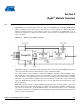
Section 2 Zigbit™ Module Overview 2.1 Overview ZigBit™ Amp is an extended-range, low-power, high sensitivity IEEE 802.15.4/ZigBee OEM module, which occupies less than a square inch of space. Based on a solid combination of Atmel's latest MCU Wireless hardware platform, power amplifier and low-noise amplifier, the ZigBit Amp offers an unmatched combination of superior radio performance, ultra-low power consumption and exceptional ease of integration. Figure 2-1. ATZB-A24-UFL/UN 0 Block Diagram VCC (1.
Zigbit™ Module Overview To jumpstart evaluation and development, Atmel also offers a complete set of evaluation and development tools. The new ZigBit Amp Development Kit [7] (ATZB-DK-A24) comes with everything you need to create custom applications featuring ZigBit Amp module. The kit features MeshBean development boards with an easy-to-access extension connector for attaching third party sensors and other peripherals, and a JTAG connector for easy application uploading and debugging.
Section 3 Specifications 3.1 Electrical Characteristics 3.1.1 Absolute Maximum Ratings Table 3-1. Absolute Maximum Ratings(1)(2) Parameters Min Max Voltage on any pin, except RESET with respect to Ground -0.5V VCC + 0.5V DC Current per I/O Pin 40 mA DC Current DVCC and DGND pins 300 mA Input RF Level +5 dBm Notes: 1. Absolute Maximum Ratings are the values beyond which damage to the device may occur. Under no circumstances must the absolute maximum ratings given in this table be violated.
Specifications Current consumption actually depends on multiple factors, including but not limited to, the board design and materials, BitCloud settings, network activity, EEPROM read/write operations. It also depends on MCU load and/or peripherals used by an application. 3.1.3 RF Characteristics Table 3-3. RF Characteristics Parameters Condition Frequency Band Unit 2.4000 to 2.
Specifications Table 3-5. Module Interfaces characteristics Parameters Condition 2 I C Maximum Clock GPIO Output Voltage (High/Low) -10/ 5 mA Real Time Oscillator Frequency 3.2 Range Unit 222 kHz 2.3/ 0.5 V 32.768 kHz Physical/Environmental Characteristics and Outline Parameters Size Operating Temperature Range Operating Relative Humidity Range Note: Value Comments 38.0 x 13.5 x 2.0 mm ATZB-A24-UFL/U0 -20°C to +70°C -40°C to +85°C operational(1) no more than 80% 1.
Specifications 3.3 Pin Configuration Figure 3-2. ATZB-A24-UFL Pinout Figure 3-3. ATZB-A24-U0 Pinout ZigBit™ 2.
Specifications Table 3-6.
Specifications Table 3-6. Pin descriptions Default State after Power on Connector Pin Pin Name Description 35 AGND Analog ground 36 GPIO9/1_WR General Purpose digital input/output 9 / 1-wire interface(2)(3)(4)(7) I/O 37 UART_DTR DTR input (Data Terminal Ready) for UART.
Specifications 9. Using ferrite bead and 1 µF capacitor located closely to the power supply pin is recommended, as shown below. 10. Pins 48, 49 and 50 are featured for ATZB-A24-U0 module only. 11. In SPI mode, USART0_EXTCLK is output. In USART mode, this pin can be configured as either input or output pin. ZigBit™ 2.
Specifications 3.4 Mounting Information The below diagrams show the PCB layout recommended for ZigBit Amp module. Neither via-holes nor wires are allowed on the PCB upper layer in area occupied by the module. As a critical requirement, RF_GND pins should be grounded via several holes to be located right next to pins thus minimizing inductance and preventing both mismatch and losses. Figure 3-4. 3.
Specifications 3.6 Antenna Reference Design Multiple factors affect proper antenna match, hence, affecting the antenna pattern. The particular factors are the board material and thickness, shields, the material used for enclosure, the board neighborhood, and other components adjacent to antenna. General Recommendations: Metal enclosure should not be used. Using low profile enclosure might also affect antenna tuning. Placing high profile components next to antenna should be avoided.
Section 4 Ordering Information 4.1 Ordering Information Part Number ATZB-A24-UFLR ATZB-A24-U0R Note: Description 2.4 GHz IEEE802.15.4/ZigBee Power Amplified OEM Module with U.FL Antenna Connector 2.4 GHz IEEE802.15.4/ZigBee Power Amplified OEM Module with Unbalanced RF output Tape&Reel quantity: 200 Section 5 Agency Certifications This equipment complies with Part 15 of the FCC rules and regulations.
The ATZB A24 UFL, ATZB A24 U0 Modules has been certified for use in European Union countries. If these modules are incorporated Headquarters International into a product, the manufacturer must ensure compliance of the final product to the European harmonized EMC and low voltage/safety standards. A Declaration of Conformity must be issued for each of these standards and kept on file as described in Annex II of the Atmel Japan Atmel Europe Atmel Asia Atmel Corporation R&TTE Directive.