µTasker Document • AT91SAM7X Tutorial – Ethernet and the Simulator uTaskerV1.4_SAM7X.doc/0.03 Copyright © 2009 M.J.
www.uTasker.com µTasker – AT91SAM7X Tutorial V1.4 Table of Contents 1. 2. 3. 4. Introduction .....................................................................................................................3 Getting Started ................................................................................................................4 Testing on the Target .....................................................................................................12 Compiling the Project for the Target ...
www.uTasker.com V1.4 µTasker – AT91SAM7X Tutorial 1. Introduction µTasker is an operating system designed especially for embedded applications where a tight control over resources is desired along with a high level of user comfort to produce efficient and modular code. The operating system is integrated with TCP/IP stack and important embedded Internet services alongside device drivers and system-specific project resources.
www.uTasker.com µTasker – AT91SAM7X Tutorial V1.4 2. Getting Started You are probably itching to see something in action and so why hang around. Let’s start with something that will already impress you and your friends – no simple and basically useless demo which blinks an LED in a forever loop but something seriously professional and for real life projects very handy.
www.uTasker.com µTasker – AT91SAM7X Tutorial V1.4 ...fasten your seat belts since we are about to roll 1. Simply copy the complete µTasker folder to your PC and go to \Applications\uTaskerV1.4. This is a ready to run project directory showing a useful application using network resources (and more). 2. Move to the sub director Simulator and open the VisualStudio project workspace uTaskerV1-4.dsw. This project is in the VisualStudio 6.
www.uTasker.com V1.4 µTasker – AT91SAM7X Tutorial After making any modifications, simply compile the changes and we will be in business. 5. So now I can say EXECUTE (use F5 as short cut). You will see the simulated device working away on your PC screen. If the define SUPPORT_GLCD hasn’t been removed in config.h there will also be a simulated graphic LCD displaying some images. This should be removed later for testing on the target if there is no graphical LCD actually connected.
www.uTasker.com µTasker – AT91SAM7X Tutorial V1.4 6. OK. So at least you are convinced that it is really running our project code, but it is not exactly something to write home about. Let’s get down to more serious stuff: There are some menu items in the µTasker environment simulation window. Open “LAN | Select working NIC” and select the network card you would like the simulator to use – don’t worry, it will be shared with anything else which is already using it.
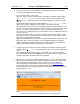
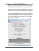
www.uTasker.com µTasker – AT91SAM7X Tutorial V1.4 This is displaying that the page has not been found on the server, which is simply due to the fact that we haven’t loaded any web pages to it yet, so we will do this as next step. Note however that the web browser is displaying the AT91 favicon. This is because this favicon is embedded in the code and not in the µFileSystem – this is explained in detail in the user file document http://www.utasker.com/docs/uTasker/uTaskerUserFiles.PDF 9.
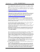
www.uTasker.com V1.4 µTasker – AT91SAM7X Tutorial second time (should your want to reset the value before we commit it to (simulated) FLASH click on “Reset changes”, otherwise click on “Save changes”. The device is commanded to be reset at this point after a short delay of about 2 seconds to allow it to complete the web page serving. The simulator will open a dialog box to indicate that it has been terminated with a reset: Figure 3.
www.uTasker.com µTasker – AT91SAM7X Tutorial V1.4 MAC address. Just start the simulator again and repeat this step. While the project is waiting for the critical network changes to be validated you will notice that the LCD doesn’t display anything. As soon as the validation sequence has been completed also the LCD display demonstration will start running as normal. 12.
www.uTasker.com V1.4 µTasker – AT91SAM7X Tutorial Do a quick test: Hover your mouse over the port PB22 in the simulator – it will tell you which pin it is on your device. Now click – this has toggled the simulated input (each time you click, it will change state again) – leave it at the low state ‘0’, displayed as ‘v’. Now refresh the I/O web page by clicking in the Refresh button. What is the web page now displaying? If it is behaving correctly it will of course be displaying the new port input state.
www.uTasker.com V1.4 µTasker – AT91SAM7X Tutorial software using this method (as well as by FTP and even USB). For further details about using this capability on the SAM7X see the document http://www.utasker.com/docs/uTasker/BM-Booloader_for_SAM7X.
www.uTasker.com µTasker – AT91SAM7X Tutorial V1.4 code so are recommended for professional work as is Rowley Crossworks if the GCC compiler is preferred. There are evaluation versions available from all suppliers - which are generally time or code size limited - for anyone wanting to get a feel for the product, otherwise it should be possible to get the code up and running with any other compiler without too much hassle, but it will involve setting up an equivalent project.
www.uTasker.com V1.4 µTasker – AT91SAM7X Tutorial 4.1. Compiling with GCC The project is delivered with a bat file and make file so that the project can be simply compiled with the GNU compiler. It is recommended to use the Codesourcery g++ build, which is available as a free Lite edition at http://www.codesourcery.com/ Compiling with GCC is also greatly simplified when working from VisualStudio by adding the step as a post build step to the normal simulator compile process.
www.uTasker.com V1.4 µTasker – AT91SAM7X Tutorial 5. Downloading the Code to the Target The following explains how to download the FLASH based target code to the ATMEL AT91SAM7X-EK using the SAM-BA utility from ATMEL. The SAM-BA utility can be downloaded from the ATMEL web site http://www.at91.com/ as part of the AT91-ISP tool package. Once you have installed the tool package you can start.
www.uTasker.com V1.4 µTasker – AT91SAM7X Tutorial You should be done within a few minutes…. Are you surprised that it behaves the same as the simulator? You shouldn’t really be because that is exactly what the simulator is all about. It allows you to test your real code in real time and once it is working as you want it to, then you can transfer it to the real target. In fact you will find that your real target is not really necessary for most of your development work.
www.uTasker.com µTasker – AT91SAM7X Tutorial V1.4 7. A Tour through the Demo Web Server Now that you have the possibility to simulate the demo and also run it on the target hardware it is time to take a more detailed look at what it does and then how it all works. The demo is designed to give you a practical platform to use as a basis for your own developments so it would be good to know how it can be best modified to suite your own needs. 7.1. Menu Figure 5.
www.uTasker.com µTasker – AT91SAM7X Tutorial V1.4 Software version – this is a string which is defined in application.h. It is also disabled so that it cannot be modified via the web side. Device ID – this is a string defined in the cParameters structure in application.c. The default value can be set in code and also modified via the web page.
www.uTasker.com V1.4 µTasker – AT91SAM7X Tutorial 7.2. LAN configuration This side is a very critical side since it allows important Ethernet settings to be modified. The first time the device is started, the default MAC address – defined in the cParameters structure in application.c - is 0-0-0-0-0-0. It can be changed just once, after which it is displayed as disabled. This is because it is normally necessary to program a new device with a unique MAC address which should normally never be changed again.
www.uTasker.com µTasker – AT91SAM7X Tutorial V1.4 They have not yet been committed to memory and the previous setting can be returned by clicking on “Reset changes”. Once you are sure that the modifications are correct, they are saved to flash memory by clicking on “Save changes”. This will cause also a reset of the device after a delay of about 1 second and it will be necessary to establish a new connection to the device using its new settings and validate the changes.
www.uTasker.com V1.4 µTasker – AT91SAM7X Tutorial 7.3. Serial Configuration This web page allows the debug interface UART in the SAM7X to be set. See the UART User’s guide for some more details of this interface: http://www.utasker.com/docs/uTasker/uTaskerUART.PDF Figure 7. µTasker web server showing the serial interface configuration page uTaskerV1.4_SAM7X.doc/0.03 21/36 31.07.
www.uTasker.com µTasker – AT91SAM7X Tutorial V1.4 7.4. Statistics The statistics window opens in a separate window and displays a table of the number of Ethernet frames counted by the Ethernet task. These are classified according to whether they were transmitted, received for the local IP address or received as broadcast frames and divided into IP protocol types. Since the values can continue to change, the user can update the window by clicking on the “Refresh” button.
www.uTasker.com V1.4 µTasker – AT91SAM7X Tutorial 7.5. I/O Page The I/O window was discussed in step 11 of the tutorial and will not be discussed in any more detail here. 7.6. Administration Side On this page the FTP server can be activated and deactivated. See also step 12 of the tutorial. Figure 9.
www.uTasker.com µTasker – AT91SAM7X Tutorial V1.4 A further action is “Restore factory settings” which returns the default settings as defined in application.c. This also provokes a reset of the device and if the default settings cause the network values to be modified it will automatically start a three minute validation period meaning that it will also be necessary to establish a connection using the ‘factory settings’ and validate them before the original ones will become permanent.
www.uTasker.com µTasker – AT91SAM7X Tutorial V1.4 7.7. LCD Side When the graphical LCD support is enabled (define SUPPORT_GLCD in config.h). The LCD page will display the present LCD content. It also allows the user to post am image to be displayed on the graphical LCD. Figure 10. LCD page showing the present LCD image For full details about the graphical LCD support in the project please consult the LCD User’s Guide at http://www.utasker.com/docs/uTasker/uTaskerLCD.PDF uTaskerV1.4_SAM7X.doc/0.
www.uTasker.com µTasker – AT91SAM7X Tutorial V1.4 7.8. Email Configuration Side The standard set of web pages loaded to the SAM7X does not include a setup page for the SMTP server but an alternative page can be temporarily loaded to perform this. For more details see the document http://www.utasker.com/docs/uTasker/uTaskerSMTP.PDF The SMTP configuration can be performed on this web page corresponding to the email provider’s requirements. The page KEmailSetup.htm has been loaded in place of Kadmin.
www.uTasker.com µTasker – AT91SAM7X Tutorial V1.4 7.9. Dynamic Content Generation Side The alternative web page E_multiplication_table.htm (from \Applications\uTaskerV1.4\WebPages\WebPagesSAM7X\AlternativePages) replaces the statistics page and demonstrates a multiplication table which is generated on demand.. For full details of this operation see the document http://www.utasker.com/docs/uTasker/uTaskerV1.3_Content_Generation.PDF Figure 12. Dynamically generated multiplication table uTaskerV1.4_SAM7X.
www.uTasker.com 8. µTasker – AT91SAM7X Tutorial V1.4 Developing – Testing - Debugging The demo project is designed to demonstrate a typical use of the operating system and TCP/IP stack. It is useful in itself as a starting point for many applications and this section looks at the support for developing, testing and debugging your own applications. Until now you haven’t actually had to develop anything since the project is delivered fully functional.
www.uTasker.com V1.4 µTasker – AT91SAM7X Tutorial Now do the following steps: 1. Start the demo project simulation as described in the first tutorial. 2. Open a DOS window and prepare the PING command “ping 192.168.0.3”. 3. Start Wireshark and start monitoring the traffic on your local network (Capture | Start -> OK). 4. Enter return in the DOS windows so that the PING test is started. 5. Wait until the PING test has completed; there are normally 4 test messages sent. 6.
www.uTasker.com V1.4 µTasker – AT91SAM7X Tutorial Repeat the ping test from the DOS window and the execution will stop at the breakpoint which you set in the interrupt routine. Since there will be no answer to the ping test because our code has been stopped, the ping test(s) will fail, but we don’t worry about that since we have caught the event which we are going to use to analyse the flow through the driver, memory, the operating system and the ICMP routine.
www.uTasker.com V1.4 µTasker – AT91SAM7X Tutorial Double click on the word ucSAM7X so that it becomes highlighted and then drag it into the watch window (Shift F9 opens a quick watch window). Expand the structure by clicking on the cross to the left of the name and you will see the various internal peripheral divided into sub-blocks. EMAC_ISR is in the sub-block usSimMAC so we also expand this sub-structure by clicking on the cross left of its name.
www.uTasker.com µTasker – AT91SAM7X Tutorial V1.4 Now it is not exactly easy to understand the data but you should just be able to make out the MAC address at the beginning and the content of the ping test usually consists of abcdefghijk… which is easily recognised. (Warning: it is possible that the frame which you actually captured is not the ping test but some other network activity, or even an ARP frame if the PC sending the ping had to re-resolve its MAC address.
www.uTasker.com µTasker – AT91SAM7X Tutorial V1.4 If you continue to step through the routine you will see that the IP frame is interpreted to see whether we are being addressed, it may cause our ARP cache to be updated and the check sum of the IP frame will also be verified. To return without stepping all the way you can use SHIFT F11 to return to the ETHERNET task code, where the protocol type is checked. E.
www.uTasker.com µTasker – AT91SAM7X Tutorial V1.4 This transmission activation takes place in the file sam7x.c in the function fnStartEthTx() so search for it and set a break point there. Once the program reaches this point it will stop and you can see which registers are set up and verify that all is correct. Here you will also see that the simulator comes into play once the data is ready and the registers have been set up correctly.
www.uTasker.com µTasker – AT91SAM7X Tutorial V1.4 1. When an Wireshark recording is played back, the internal NIC is closed so that there is no disturbance from the network. 2. The Wireshark recording can be repeated after it has terminated. There is no limit as to the number of times it can be repeated. Useful for incremental testing of a new piece of code… 3. After an Ethernet playback it is necessary to restart the simulator to use the simulator with the network again. 4.
www.uTasker.com V1.4 µTasker – AT91SAM7X Tutorial 10. Conclusion This tutorial first introduced the µTasker simulator’s capabilities to execute the demo project software on a simulated SAM7X. It showed the basics of working with the simulator and its Ethernet capabilities before turning attention to running the same project on a target board.