
File ata5283


6
ATA5283 [Preliminary]
4598D–AUTO–03/04
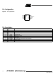
The following diagrams show the delay of the data signal as a function of the antenna
Q-factor.
Figure 6. Turn On Delay Time (t
ON
) versus Antenna Q-Factor
Figure 7. Turn Off Delay Time (t
off
) versus Antenna Q-Factor
Data Output The data output N_DATA outputs the demodulated and digitized LF signal according to
the envelope of the antenna input signal. In the standby mode the N_DATA output is
disabled and set to level 1. It is enabled by the wake-up signal and it outputs 1 level if
the IC detects the carrier signal and a 0 level during the gaps (see Figure 3).
As the circuit does not check the received data (except the preamble), it is up to the user
to choose the kind of encoding (pulse distance, Manchester, bi-phase...) wanted.
Wake-up Signal The wake-up signal (N_WAKEUP) indicates that the ATA5283 has detected the end of a
preamble signal and has left the standby mode. It can be used as a wake-up or a chip
select signal for an external device (see Figure 3).
After a preamble is detected the first valid gap (Start Gap) sets the N_WAKEUP output
to low and enables the data output N_DATA. The N_WAKEUP holds the low level until
the IC is reset to the standby mode by a reset signal.
0
50
100
150
200
250
0 102030 40 50
Q-factor
t
on
(µs)
Min.
Typ.
Max.
f
field
= 125 kHz
0
20
40
60
80
100
120
140
160
180
200
01020304050
t
off
(µs)
Min.
Typ.
Max.
f
field
= 125 kHz
Q-factor