
Specifications


34
4929A–AUTO–10/06
ATA6264 [Preliminary]
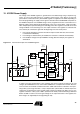
Necessary for operation:
V
SAT
> 7.5V, V
INT
= 3.7V to 5.47V, V
CORE
< V
PERI
+ 0.3V
Operating conditions of all other supply pins:
V
K30
, V
EVZ
and V
CORE
are within functional range limits, T
j
= –40°C to 150°C
Other pins:
As defined in Section 4. ”Functional Range” on page 8.
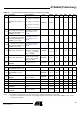
Table 11-1. Electrical Characteristics – VPERI Power Supply
No. Parameters Test Conditions Pin Symbol Min Typ. Max. Unit Type*
10.1
Voltage level at VSAT to enable
VPERI regulator
VSAT V
VSAT
6.77 7.2 V A
10.2
Hysteresis at VSAT to disable
VPERI regulator
VSAT V
VSAT
0.2 0.5 V A
10.3 Output voltage #1
V
VPERI1
programmed,
band-gap tolerance
included
VPERI V
VPERI
–3.6% 5 +4% V A
10.4 Output voltage #2
V
VPERI2
programmed,
band-gap tolerance
included
VPERI V
VPERI
–4% 3.3 +3% V A
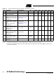
10.5 Output current V
VSAT
= 7.5V to 12.5V VPERI I
VPERI
–100 mA A
10.6 Short-circuit current VPERI I
VPERI
–200 –110 mA A
10.7 Line regulation
V
VSAT
= 8V to 12.5V
I
PERI
= –1 mA to –100 mA
(I
PERI
is constant during
measurement)
VPERI V
VPERI
–10 +10 mV A
10.8 Load regulation
V
SAT
= 8V to 12.5V (V
VSAT
is constant during
measurement)
I
PERI
= –1 mA to –100 mA
VPERI V
VPERI
–10 +10 mV A
10.10 Supply voltage rejection
I
PERI
= –100 mA,
f = 100 kHz – 20 MHz,
C
PERI
= 47 µF + 100 nF
(ceramic)
40 dB D
*) Type means: A = 100% tested, B = 100% correlation tested, C = Characterized on samples, D = Design parameter