
Specifications

57
4929A–AUTO–10/06
ATA6264 [Preliminary]
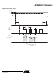
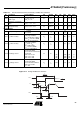
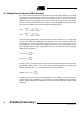
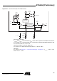
Figure 17-2. Timing LIN/ISO 9141 Interface
16.37
Propagation delay K
1
high to
RxD
1
=high
Measured from
K
1
=0.6× V
K30
to
RxD
1
=LtoH
K
1
t
PDkH
4µsA
16.38
Symmetry of transmitter
delay
t
SYM_T1
=t
PDtL
–t
PDtH
K
1
t
SYM_T1
–1 1 µs A
16.39
Symmetry of receiver
propagation delay
t
SYM_R1
=t
PDkL
–t
PDkH
K
1
t
SYM_R1
–1 1 µs A
LS Driver Mode
16.40 K
x
output voltage drop
I
Kx
=40mA
I
Kx
=20mA
K
x
V
Kx
1.7
1.2
VA
16.41 K
x
switch-on delay
(x = 1, 2), measured from
rising edge of SSQ to
V
Kx
= 16.40V, R
Kx
=250Ω to
K30, C
Kx
= 3.3 nF to GNDB
K
x
t
Kx
50 µs A
16.42 K
x
switch-off delay
(x = 1, 2), measured from
rising edge of SSQ to
V
Kx
=0.9× V
K30
,
R
Kx
= 250Ω to K30,
C
Kx
= 3.3 nF to GNDB
K
x
t
Kx
10 µs A
16.43 K
x
leakage current
(x = 1, 2), output driver
deactivated, AMUX
measurement activated and
deactivated
K30 = 5.5V to 15V
K30 > 15V to 25V
K30 > 25V to 40V
K
x
I
Kx
–10
–10
–10
+100
+160
+260
µA
µA
µA
A
A
A
16.44 K
x
leakage current
(x = 1, 2), output driver
deactivated, AMUX
measurement deactivated
K30 = 5.5V to 40V
K
x
= –25V
K
x
I
Kx
–150 +10 µA A
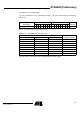
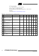
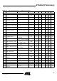
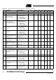
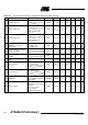
Table 17-1. Electrical Characteristics (Continued)– LIN/ISO 9141 Interfaces
No. Parameters Test Conditions Pin Symbol Min Typ. Max. Unit Type*
*) Type means: A = 100% tested, B = 100% correlation tested, C = Characterized on samples, D = Design parameter
90%
Baudrate
Baudrate =
t
on
+ t
off
2
60%
40%
10%
t
PDtL
V
K
V
TXD
V
RXD
2
t
PDkL
t
PDkH
t
PDtH