RFID Application Kit ATAK2270 ....................................................................................................................
Table of Contents Section 1 Introduction................................................................................................................. 1-1 1.1 RFID Products Promoted by ATAK2270 Kit ...................................................................... 1-1 1.2 Included Hardware Components ....................................................................................... 1-1 1.3 Equipment Needed ....................................................................................
Table of Contents (Continued) 5.3 5.4 ii 4871E–RFID–04/08 Transponder Type Software Interface Description ............................................................ 5-6 5.3.1 TK5530/e5530 Read-only Transponder Menu .................................................... 5-6 5.3.2 TK5552/T5552 Read/Write Transponder............................................................. 5-7 5.3.3 TK5551 Read/Write Transponder........................................................................ 5-9 5.3.
Section 1 Introduction 1.1 RFID Products Promoted by ATAK2270 Kit The RFID application kit (ordering code ATAK2270) promotes the key features of various RFID products from Atmel®. The following products are supported by the kit: 1.2 1.
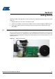
Section 2 Getting Started Build up the RFID reader application system according to the configuration shown on the cover and in Figure 2-1: 1. Plug the antenna into the socket of the interface board. 2. Connect a serial RS232 cable between the RS232 connector and either COM1 or COM2 of the PC. 3. Connect the supply line from the 12V power source to the jack connector. Alternatively use the mains SMPS. 2.
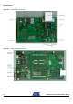
Getting Started Figure 2-2. Antenna Interface Board Figure 2-3.
Getting Started 2.2 Software Installation The ATAK2270 host installation software as well as the related datasheets and documentation are provided by the CD-ROM included in the kit. Furthermore, the up-to-date software and documentation are available via the web. Execute the setup.exe file found on the CD-ROM to launch the installation and generate the ATAK2270.exe program file.
Section 3 Description of the Application Board System 3.1 System Overview The ATAK2270 application board unit (Figure 2-3) consists of a ready-to-run standard microcontroller main board equipped with the Atmel AVR® microcontroller ATmega8515L, combined with a piggybacked antenna interface board containing the U2270B reader IC.
Description of the Application Board System 3.3.1 Frequency Tuning Mode Selection The reader interface has a built-in frequency tuning feature. By the host software, the resonant frequency of the LC antenna circuit can be switched in four steps. Therefore the board is equipped with two stages of high-voltage transistor switches to tune the resonator via switched capacitors. Table 3-1.
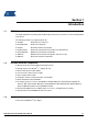
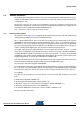
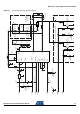
RFID Application Kit ATAK2270 User Manual X2/9 X2/10 X1/11 X1/7 X1/3 X2/5 M2 DZ1 LD1 Power R1 Green M12 Data in Data out M11 C3 R2 IN LD4 RFon 7808 U2 R7 C6 Yellow 10 C4 6 16 7 1 3 2 13 12 11 OUT M4 VS 14 R15 LD2 TUNE1 CFE HIPASS DGND GND OE OUTPUT STANDBY VBATT VEXT DVS MS 5 Red R17 R16 COIL1 COIL2 INPUT RF 15 R9 9 8 4 BF820 T1 R18 R11 R10 BAS21 D3 D2 BAS21 CANT2 LD3 TUNE2 BAS21 D6 R19 Red R21 R20 C9 BF820 T2 R22 1 2 3 J3
Description of the Application Board System 3.3.3 3.3.3.1 3.3.3.2 3.3.3.3 Antenna Interface Parts List U1 U2 U2270 B LM7808 SO16 TO220 D1 D2 D3 D4 D5 D6 D7 DZ1 BAS21 BAS21 BAS21 BAS21 BAS21 BAS21 BAS21 BZX84C SOT23 SOT23 SOT23 SOT23 SOT23 SOT23 SOT23 SOT23 LD1 LD2 LD3 LD4 TLMC3100 (green) TLMT3100 (red) TLMT3100 (red) TLMA3100 (yellow) PLCC2 PLCC2 PLCC2 PLCC2 BF820 BF820 SOT23 SOT23 3.6 kΩ 360Ω 10 kΩ 1 kΩ 68 kΩ 43 kΩ 1 kΩ 390 kΩ 75 kΩ 100 kΩ 24Ω 1 kΩ 3.6 kΩ 1.5 kΩ 100Ω 1 kΩ 3.6 kΩ 1.
Description of the Application Board System 3.3.3.5 Capacitors CANT1 CANT2 CTUNE1 CTUNE2 C3 C4 C5 C6 C7 C8 C9 3.3.3.6 1.8 nF II 120 to 180 pF/100V 330 (270) pF/100V 150 pF/100V 330 pF/100V 10 µF/16V 22 µF/16V 22 µF/16V 220 nF 6.8 nF/100V 2.2 nF/100V 4.
Section 4 Basic Transponder Functionality Getting Started 4.1 System Installation 1. Install the host software according to the instructions in Section 2.2. 2. Connect the application board unit with the host PC using the RS232 serial cable included in the kit. 3. Connect a 12V (AC or DC) power supply to the board using the jack connector cable. The power-on status is indicated by green LEDs labelled Power located, one each, on the interface and main board. 4. Start the host software on the host PC.
Section 5 Host Software Figure 5-1. 5.
Host Software 5.2 Start Window The host software menu bar has five menus: Setup, Option, Application, Exit, and Info. 5.2.1 Setup Select the appropriate transponder in the Setup -> Transponder menu (Figure 5-2). The user interface displayed depends on the transponder chosen. Figure 5-2. Transponder Menu In the submenu COM-Port, select the RS232 serial port used to communicate with the RFID application kit (COM-Port).
Host Software Figure 5-4. Tuning Menu Table 5-1. Tuning Stage LED Indication Tune2 Tune1 Frequency 0 0 High 0 1 Semi High 1 0 Semi Low (default) 1 1 Low Select the submenu RF-Field to switch the antenna’s RF field ON or OFF. The current status is indicated by the yellow LED, RF On, on the interface board. ON is the default value. Clicking Demoboard Reset resets the application board and returns all changes in the option menu to the default values.
Host Software 5.2.3.1 Write Bit String The input text box in theWrite Bit String window can be used to enter programming data, which can be sent to any block. The bit string entered can be freely composed; therefore, it is important to consider the bit sequence, specified above the text box. For the supported transponder types, typical default configurations can be displayed in the text box by clicking a corresponding Load standand block... buttons.
Host Software 5.2.3.2 Timing Test If specific antennas have to be matched to a transponder IC, the Timing Test feature can be used to determine the appropriate write timing needed for OOK data downlink. The write time ranges for logical one, logical zero, and gap can be defined. When the Start Test button is clicked, data is written to the tag starting with the minimal time values. Following this, the programmed data content will be read back and verified, and the results displayed in the window.
Host Software 5.3 Transponder Type Software Interface Description 5.3.1 TK5530/e5530 Read-only Transponder Menu Figure 5-9. TK5530 Read Tab Selecting Transponder >TK5530/e5530 from the Setup menu, opens the the TK5530 user interface. A Read tab is displayed. The read tab is divided into two areas – Configuration Setup and Read Timings.
Host Software 5.3.2 TK5552/T5552 Read/Write Transponder Figure 5-10. TK5552 Read Tab Selecting Transponder >TK5552/T5552 from the Setup menu, opens the the TK5552 user interface. Two tabs are available – Read and Write. The Read tab is divided into two areas – Configuration Setup and Read Timings. The following parameters can be configured in the Configuration Setup area: Bitrate: Rf/16 and Rf/32 Coding: Manchester and PSK ID-Code Length: Block0, Block1, Block1 to 2, Block 1 to 3, ...
Host Software To read the transponder, click the Read button. If a Header Signature is used, ensure that the related Header has already been programmed into the transponder from the Write tab. Decoding is caried by transferring the Configuration Setup and Read Timing settings to the microncontroller on the RFID application kit via RS232 interface. The incoming data stream is decoded to binary values sent to the PC. The Default button restored the default settings.
Host Software 5.3.3 TK5551 Read/Write Transponder Figure 5-12. TK5551 Read Tab Selecting Transponder >TK5551 from the Setup menu, opens the the TK5530 user interface. Two tabs are available – Read and Write. The Read tab is divided into two areas – Configuration Setup and Read Timings. The following parameters can be configured in the Configuration Setup area: Bitrate: Rf/8, Rf/16, Rf/32, Rf/40, Rf/50, Rf/64, Rf/100 and Rf/128 Coding: Manchester, Biphase, direct, PSK..., FSK,...
Host Software To change the configuration setup, click the Configure Transponder button to program the configuration block of the transponder. (The transponder should be placed close to the application board antenna) The timing parameters for decoding can be set in the Read Timing area. For standard read mode, the default values can be used. To read the transponder, click the Read button.
Host Software 5.3.4 T5557/ATA5567 Multifunction Read/Write Transponder The ATA5567 offers an improvement over T5557’s slow power-on behavior. Apart from this difference, both transponders are functionally identical and thus can be managed by same user interface. Both transponders are backward compatible to the older T5551/TK5551 version. Therefore, they can be operated in the Compatible or Basic Mode. Figure 5-14. T5557/ATA5567 Mode Selection 5.3.4.
Host Software Figure 5-15. Extended Mode Main Read Tab Selecting Extended Mode displays the Read tab (Figure 5-15). The Read tab is divided into two areas – Configuration Setup and Read Timings. 5.3.4.3 Configuration Setup 5-12 4871E–RFID–04/08 Bitrate: Rf / (n + 2) for n = 0 to 126 (default setting Rf/32) Coding: Manchester, Biphase 1('50), Biphase 2 ('57), Direct, PSK..., FSK,...
Host Software POR-Delay: In the default setting, the modulation starts after 192 clock cycles (1.5 ms at 125 kHz) are recognized. When actively selecting POR-Delay, the modulation delay measures 8382 clock cycles (67 ms at 125 kHz) Fast Write: When Fast Write is selected, the write times in the Write menu are reduced by half OTP: If OTP is set, all memory blocks are write-protected These configuration parameters are sent to the transponder when the Configure Transponder button is clicked.
Host Software 5.3.4.4.2 Traceability Data The Traceability Data button allows direct access to page 1, which contains the 64-bit traceability data as defined by ISO/IEC 15963-1. Refer to section Section 5.4.3 ”Readout Manufacturer (Traceability) Data” for further details. Exit Use the Cancel button to terminate T5557 operation. 5.3.4.5 Data Write Figure 5-17. T5557 Write Tab The Write tab has two sections; Write Setup and Write Timing .
Host Software 5.3.5 ATA5570 Multifunction Read/Write Transponder with Sensor Input The ATA5570 is derived from the T5557; however, it is enhanced by an additional sensor input. Depending on the connected sensor resistance, the uplink data is sent either in direct or inverse mode. Table 5-2. Data Mode Depending on Resistance Resistance Pin 4-5 Jumper J2 Sent Data > 140 kΩ Open Direct < 70 kΩ Closed Inverse To promote the sensor functionality, a special application board is available, ATAB5570.
Host Software 5.3.6 ATA5577 Enhanced Read/Write Transponder with AFE-Options When the ATA5577 transponder is selected, it can be operated in either Basic Mode (compatible with the T5557/ATA5567/TK5551) or in Extended Mode for enhanced functionality. Figure 5-20. ATA5577 Mode Selection 5.3.6.1 Basic Extended Mode Selection The ATA5577 user guide describes the software functionality using the Extended Mode. Functions that are not supported by Basic Mode are indicated.
Host Software The structure of the ATA5577 user interface differs from the other transponder types. In the Setup window, four tabs – Transp. Settings, Write, Read and ISO 11784 – and the Downlink section allow the configuration, reading, writing and programming and reading transponder according ISO 11784/85 standard. 5.3.6.2 Downlink Settings The Downlink section, above the tabs, indicates the current downlink mode from the reader to the transponder.
Host Software Not released in Basic Mode: Terminator: – Basic Mode Sequence Terminator – Extended Mode Sequence Start Marker Terminator Initial.
Host Software 5.3.6.4 Selecting Write tab Figure 5-22. ATA5577 Write Tab In the Extended Mode, the Fast Write check box in the Downlink section is released (This is the only difference to the Write tap in Basic Mode). However the Fast Write feature makes less sense for programming via resonating antenna coupling, due to the needed time duration determined by the gap time of the ON/OFF Keying (OOK). Nevertheless, the feature is performed by the software.
Host Software 5.3.6.5 Selecting Read tab Figure 5-23. ATA5577 Read Tab The Read menu displays the content of the data blocks 1-7. To read data from an unknown transponder, the configuration of the transponder must be first known and entered in the Bitrate, Coding, MaxBlock and Synchronization fields. The default Read Timing is derived from the Bitrate setting and normally suitable for most transponder applications. The synchronization of the transponder can be configured in the Synchronization area.
Host Software Figure 5-24. Direct ccess Dialog Box In the Read tab, an AOR button is displayed if AOR has been configured in the Transp. Settings tab (see Figure 5-21). The execution of the command initiates the Answer on Request procedure (Section 5.4.2 ”Answer On Request AOR Mode” ). Click the Reset Transponder button to initialize a reset. This initializes the standard Read Mode of the transponder. Transponder manufacturer data can be read by clicking the Traceability Data button (Section 5.
Host Software The ISO 11784 Setting tab allows the programming and reading of a transponder according to the ISO standard 11784/85 used for animal ID or waste logistics. Opening the ISO 11784 Settings tab, the reader automatically changes the field frequency from 125 kHz to 134.2 kHz as specified by standard. The ISO 11784 Settings tab has two sections: Program Transponder and Read Transponder.
Host Software 5.4 Operating Common Transponder Features 5.4.1 Password PWD Mode The transponder can be protected from unauthorized overwriting of memory data using passwords. If the transponder is configured in password mode, each block write command sent to the transponder has to be expanded by the expected password as specifed by the content of block7.
Host Software 5.4.2 Answer On Request AOR Mode The AOR feature is used to address an individual transponder, among others in a common field. For AOR mode to function, transponders must be also be configured for password mode. Each transponder has to be programmed with a unique password. If the reader sends an AOR wake-up sequence that matches a password of one transponder present in the field, the transponder starts to transmit its ID code continuously.
Host Software 5.4.3 Readout Manufacturer (Traceability) Data The Traceability Data button allows direct access to block 1 an 2 of page 1 which contain the 64-bit traceability data programmed and locked by Atmel during production.
Headquarters International Atmel Corporation 2325 Orchard Parkway San Jose, CA 95131 USA Tel: 1(408) 441-0311 Fax: 1(408) 487-2600 Atmel Asia Room 1219 Chinachem Golden Plaza 77 Mody Road Tsimshatsui East Kowloon Hong Kong Tel: (852) 2721-9778 Fax: (852) 2722-1369 Atmel Europe Le Krebs 8, Rue Jean-Pierre Timbaud BP 309 78054 Saint-Quentin-enYvelines Cedex France Tel: (33) 1-30-60-70-00 Fax: (33) 1-30-60-71-11 Atmel Japan 9F, Tonetsu Shinkawa Bldg.