
Board User Guide


Using the ATAVRAUTO200
ATAVRAUTO200 User Guide 2-5
7698A–AUTO–01/07
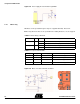
Table 2-1. LIN ressources
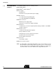
Figure 2-3. LIN transceiver and power supply
Note: The LIN transceiver undervoltage protection can be disabled by removing the
NISP jumper.
Note: The NISP jumper has to be removed when programming.
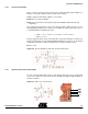
2.4.2 Power supply measurement
The voltage measurement is realized with a bridge of resistors. The read value is 0.281
of the LIN power supply (47 KΩ / (47 KΩ + 120 KΩ)). Input voltage on channel 1 of the
ADC is limited to 5.1V by a zener diode. This will give a voltage reading range from 0 to
18.1V with Vcc as reference.
The power supply measurement can be performed using the A/D converter. See the
ATmega48/88/168 datasheet for how to use the ADC. The input voltage value (V
IN
) is
calculated with the following expression:
Where: V
IN
= Input voltage value (V)
V
ADC7
= Voltage value on ADC-1 input (V)
Function Port State Description
LIN_NSLP PD2 Low LIN transceiver in Sleep mode
High LIN transceiver in normal mode
NRES_LIN PC6 Low Perform MCU reset when NISP Jumper is inserted
High No Action
+VBat
G
N
D
L
I
N
V
IN
3.55 V
ADC
1
×=