
Datasheet

152
8011O–AVR–07/10
ATmega164P/324P/644P
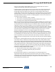
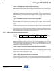
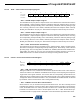
14.10 Timer/Counter Prescaler
Figure 14-12. Prescaler for Timer/Counter2
The clock source for Timer/Counter2 is named clk
T2S
. clk
T2S
is by default connected to the main
system I/O clock clk
IO
. By setting the AS2 bit in ASSR, Timer/Counter2 is asynchronously
clocked from the TOSC1 pin. This enables use of Timer/Counter2 as a Real Time Counter
(RTC). When AS2 is set, pins TOSC1 and TOSC2 are disconnected from Port C. A crystal can
then be connected between the TOSC1 and TOSC2 pins to serve as an independent clock
source for Timer/Counter2. The Oscillator is optimized for use with a 32.768 kHz crystal. By set-
ting the EXCLK bit in the ASSR a 32 kHz external clock can be applied. See ”ASSR –
Asynchronous Status Register” on page 157 for details.
For Timer/Counter2, the possible prescaled selections are: clk
T2S
/8, clk
T2S
/32, clk
T2S
/64,
clk
T2S
/128, clk
T2S
/256, and clk
T2S
/1024. Additionally, clk
T2S
as well as 0 (stop) may be selected.
Setting the PSRASY bit in GTCCR resets the prescaler. This allows the user to operate with a
predictable prescaler.
14.11 Register Description
14.11.1 TCCR2A – Timer/Counter Control Register A
• Bits 7:6 – COM2A1:0: Compare Match Output A Mode
These bits control the Output Compare pin (OC2A) behavior. If one or both of the COM2A1:0
bits are set, the OC2A output overrides the normal port functionality of the I/O pin it is connected
to. However, note that the Data Direction Register (DDR) bit corresponding to the OC2A pin
must be set in order to enable the output driver.
10-BIT T/C PRESCALER
TIMER/COUNTER2 CLOCK SOURCE
clk
I/O
clk
T2S
TOSC1
AS2
CS20
CS21
CS22
clk
T2S
/8
clk
T2S
/64
clk
T2S
/128
clk
T2S
/1024
clk
T2S
/256
clk
T2S
/32
0
PSRASY
Clear
clk
T2
Bit 7 6 5 4 3 210
(0xB0)
COM2A1 COM2A0 COM2B1 COM2B0 – – WGM21 WGM20 TCCR2A
Read/Write R/W R/W R/W R/W R R R/W R/W
Initial Value 0 0 0 0 0 0 0 0