
Datasheet

343
8011O–AVR–07/10
ATmega164P/324P/644P
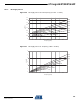
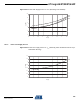
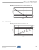
Figure 26-10. Idle Supply Current vs. V
CC
(Internal RC Oscillator, 128 kHz).
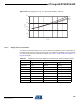
26.1.3 Supply Current of IO modules
The tables and formulas below can be used to calculate the additional current consumption for
the different I/O modules in Active and Idle mode. The enabling or disabling of the I/O modules
are controlled by the Power Reduction Register. See ”PRR – Power Reduction Register” on
page 48 for details.
85°C
25°C
-40°C
0
0.02
0.04
0.06
0.08
0.1
0.12
1.5 2 2.5 3 3.5 4 4.5 5 5.5
V
CC
(V)
I
CC
(m
A)
Table 26-1. Additional Current Consumption for the different I/O modules (absolute values)
PRR bit Typical numbers
V
CC
= 2V, F = 1 MHz V
CC
= 3V, F = 4 MHz V
CC
= 5V, F = 8 MHz
PRUSART1 6.0 µA 38.5 µA 150.0 µA
PRUSART0 7.9 µA 50.3 µA 197.0 µA
PRTWI 16.9 µA 116.2 µA 489.3 µA
PRTIM2 14.4 µA 95.8 µA 393.2 µA
PRTIM1 9.0 µA 57.3 µA 234.8 µA
PRTIM0 5.1 µA 33.3 µA 132.5 µA
PRADC 18.1 µA 86.3 µA 335.3 µA
PRSPI 11.1 µA 70.5 µA 285.0 µA