
Datasheet

35
8011O–AVR–07/10
ATmega164P/324P/644P
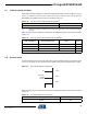
The capacitance (Ce +Ci) needed at each TOSC pin can be calculated by using:
where:
– Ce - is optional external capacitors as described in Figure 8-2 on page29
– Ci - is the pin capacitance in table 8-8 on page 33
– CL - is the load capacitance for a 32.768 kHz crystal specified by the crystal vendor
– CS - is the total stray capacitance for one TOSC pin.
Crystals specifying load capacitance (CL) higher than 8.0 pF, require external capacitors applied
as described in Figure 6-2 on page 31.
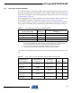
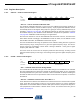
When this oscillator is selected, start-up times are determined by the SUT Fuses and CKSEL0
as shown in Table 6-9.
Note: 1. These options should only be used if frequency stability at start-up is not important for the
application.
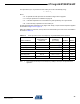
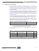
Table 6-9. Start-up Times for the Low Frequency Crystal Oscillator Clock Selection
Power Conditions
Start-up Time from
Power-down and
Power-save
Additional Delay
from Reset
(V
CC
= 5.0V) CKSEL0 SUT1..0
BOD enabled 1K CK 14CK
(1)
000
Fast rising power 1K CK 14CK + 4.1 ms
(1)
001
Slowly rising power 1K CK 14CK + 65 ms
(1)
010
Reserved 0 11
BOD enabled 32K CK 14CK 1 00
Fast rising power 32K CK 14CK + 4.1 ms 1 01
Slowly rising power 32K CK 14CK + 65 ms 1 10
Reserved 1 11
C 2 CL⋅ C
s
–=