APPLICATION NOTE Atmel AVR2016: RZRAVEN Hardware User’s Guide 8-bit Atmel Microcontrollers Features • Development kit for the Atmel® AT86RF230 radio transceiver and Atmel AVR® microcontroller • • CE, ETSI and FCC approved LCD module (Atmel AVRRAVEN): • • • • • • • AT86RF230 radio transceiver with high gain PCB antenna Dual AVR microcontrollers Dynamic speaker and microphone Atmel Serial Dataflash® User I/O section: • USART • GPIO • Relay Driver Powered by battery or external supply: • 5V to 12V exter
Table of Contents 1. General 3 2. The Atmel AVRRAVEN module ........................................................... 4 2.1 2.2 2.3 2.4 2.5 2.6 2.7 2.8 2.9 2.10 2.11 2.12 2.13 Atmel AVR Microcontrollers .............................................................................. 5 Atmel Radio Transceiver ................................................................................... 5 Antenna description ..........................................................................................
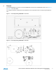
1. General The Atmel RZRAVEN kit is built from one Atmel RZUSBSTICK module and two AVRRAVEN modules. See Figure 1-1 to Figure 1-4 for further details. The complete schematics and Gerber files are available from the compressed archive accompanying this application note. Figure 1-1. Assembly drawing AVRRAVEN – front view. Figure 1-2. Assembly drawing AVRRAVEN – back view.
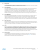
Figure 1-3. Assembly drawing Atmel RZUSBSTICK – front view. Figure 1-4. Assembly drawing RZUSBSTICK – back view. 2. The Atmel AVRRAVEN module Figure 2-1. AVRRAVEN overview. The AVRRAVEN hardware is based on two microcontrollers and one radio transceiver chip. The Atmel ATmega3290P handles the sensors and the user interface and the Atmel ATmega1284P handles the Atmel AT86RF230 radio transceiver and the RF protocol stacks. The MCUs and the radio communicate via serial interfaces.
2.1 Atmel AVR Microcontrollers Two AVR microcontrollers are found on the Atmel AVRRAVEN module. An Atmel ATmega1284P is connected to the Atmel AT86RF230 radio transceiver, and an Atmel ATmega3290P is driving the LCD. Both these devices are selected from the AVR picoPower® family, something that ensures minimal power consumption and operation down to 1.8V. Universal Synchronous and Asynchronous serial Receiver and Transmitter (USART) is used as an inter processor communication bus. 2.
2.6 Microphone The Atmel AVRRAVEN’s microphone is connected to the Atmel ATmega3290P ADC channel 0. The signal is amplified and low-pass filtered. Pulling PORTE7 low activates the microphone circuit. 2.7 Serial Dataflash A 16Mb Atmel Serial Dataflash (AT45DB161D) is connected to the ATmega3290P’s Serial Peripheral Interface (SPI). This storage is used for safe firmware images, sounds and general-purpose parameters.
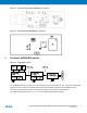
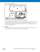
Figure 2-3. Power source selection. The Atmel AVRRAVEN has been designed to run from two 1.5V LR44 battery cells. An onboard voltage regulator makes it possible to run power the AVRRAVEN from a 5V to 12V DC source. The external voltage is applied to the two leftmost pins in the user I/O area (J401). The Atmel ATmega3290P’s ADC channel 2 is connected to a voltage divider and the external voltage supply interface. This way it is possible for the application to monitor the external operating voltage. 2.
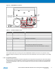
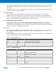
Figure 2-4. AVRRAVEN User Interfaces. Table 2-1. Interfaces available on J401. Pin number Function Comment 1 Ext. power supply, 5-12V input External power input 2 Ext. power supply 0V Connected to internal 0V 3 Relay coil positive Relay driver circuit positive 4 Relay coil negative Relay driver circuit negative 5 Voltage measure input, 0-VCC*5 Analog input via 47k/10k voltage divider 6 Voltage measure input, 0-VCC Analog input directly to ADC input.
ISP programming can be performed by connecting an ISP enabled Atmel AVR programming tool to the pin header J302 (ATmega3290P) and J205 (ATmega1284P). AVR tools like Atmel STK®500, AVRISP mkII and JTAGICE mkII can be used for this. The AVRRAVEN does not come with these headers mounted. So it is up to the user populating these. Wires could also be soldered in instead of the dual row headers. 2.12.2 Relay Interface A relay interface (Relay Positive and Negative) is available through J401.
3. ATmega1284P User I/O PCB Connection Comment N.C. J201-8 Populate R205 to connect to PC6. RTC Xtal XC202 must then be removed. PD0 J202-1 RXD0 Inter processor communication. PD1 J202-2 TXD0 Inter processor communication. PD2 J202-3 DIO or RXD1. PD3 J202-4 DIO or TXD1. PD4 J202-5 DIO. PD5 J202-6 DIO. PB2 J202-7 DIO. NB: NOT PD6! PD7 J202-8 DIO. PA0 J203-1 DIO or ADC Channel 0. PA1 J203-2 DIO or ADC Channel 1. PA2 J203-3 DIO or ADC Channel 2.
The AVR RZUSBSTICK hardware is based a USB microcontroller and a radio transceiver chip. The Atmel AT90USB1287 microcontroller handles the USB interface, the Atmel AT86RF230 radio transceiver and the RF protocol stacks. For hardware details please refer to Appendix D for the complete AVR RZUSBSTICK schematics. 3.1 AVR Microcontroller The Atmel AT90USB1287 is a device in the family of AVRs with a low and full speed USB macro with device, host and On-the-go (OTG) capabilities. 3.
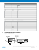
3.4.2 External Memory Interface When necessary the Atmel AT90USB1287’s 8kB of internal SRAM can be extended through the AVR external memory interface. The suggested external SRAM is 32kB and is available from address 0x8000 to 0xFFFF giving a total of 40kB when assembled. Suggested latch and RAM: • • 3.4.3 74AHC573PW BS62UV256TCP-10 Serial Interface The USART on the Atmel AT90USB1287 is routed to J4 on the Atmel RZRAVEN’s backside.
Appendix A.
Atmel AVR2016: RZRAVEN Hardware User’s Guide [APPLICATION NOTE] 8117E−AVR−07/12 14
Atmel AVR2016: RZRAVEN Hardware User’s Guide [APPLICATION NOTE] 8117E−AVR−07/12 15
Atmel AVR2016: RZRAVEN Hardware User’s Guide [APPLICATION NOTE] 8117E−AVR−07/12 16
Atmel AVR2016: RZRAVEN Hardware User’s Guide [APPLICATION NOTE] 8117E−AVR−07/12 17
Appendix B. Atmel AVRRAVEN Bill of materials Qty Designator Description 5 C205, C206, C207, C220, C221 Ceramic capacitor, SMD 0402, NP0, 50V, ±0.25pF Manufacturer Part# 1.2p 2 C201, C204 Ceramic capacitor, SMD 0402, NP0, 50V, ±5% 12p 3 C413, C414, C415 Ceramic capacitor, SMD 0402, NP0, 50V, ±10% 100p 1 C404 Ceramic capacitor, SMD 0402, X7R, 25V, ±10% 4.
Qty Designator Description Manufacturer Part# 1 Q501 General purpose SMD BJT dual NPN-PNP Philips BC847BPN 1 U303 16Mb 2.7-3.6 volt DataFlash ATMEL AT45DB161D-SU 1 U201 2.4GHz ZigBee/802.15.4 tranceiver ATMEL AT86RF230-ZU 1 U203 2kb Serial (TWI) EEPROM, AT24C02B, 1.8-5V ATMEL AT24C02B-TSU-T 1 U501 LDO 3.3V 150mA SOT23-5 (cer.
Appendix C. Atmel AVRRAVEN LCD Figure 3-4. AVRRAVEN Segments.
Table 3-2. LCD Segment description and mapping.
Appendix D.
Appendix E. Atmel RZUSBSTICK Bill of materials Qt Designator Description 1 C18 Ceramic capacitor, SMD 0402, NP0, 50V, ±0.25pF Manufacturer 1.
Appendix F. Federal Communications Commission (FCC) Statement F.1 FCC Statements F.1.1 Equipment usage This equipment is for use by developers for evaluation purposes only and must not be incorporated into any other device or system. F.1.2 Compliance Statement (Part 15.19) These devices comply with Part 15 of the FCC Rules. Operation is subject to the following two conditions: 1. 2.
Atmel Corporation Atmel Asia Limited Atmel Munich GmbH Atmel Japan G.K. 1600 Technology Drive Unit 01-5 & 16, 19F Business Campus 16F Shin-Osaki Kangyo Bldg. San Jose, CA 95110 BEA Tower, Millennium City 5 Parkring 4 1-6-4 Osaki, Shinagawa-ku USA 418 Kwun Tong Road D-85748 Garching b. Munich Tokyo 141-0032 Tel: (+1)(408) 441-0311 Kwun Tong, Kowloon GERMANY JAPAN Fax: (+1)(408) 487-2600 HONG KONG Tel: (+49) 89-31970-0 Tel: (+81)(3) 6417-0300 www.atmel.