Atmos InterCombi Installation & Servicing Instructions for HE32 (GC 47-249-01) Atmos Heating Systems West March Daventry Northants, NN11 4SA Tel: 01327 871990 Fax: 01327 871905 e-mail: sales@atmos.uk.com internet: www.atmos.uk.com Issue 22.01.
© 2010 Atmos Heating Systems The information provided applies to the product in the standard model. Atmos Heating Systems can therefore not be held liable for any damage resulting from the product specifications that deviate from the standard model. The information provided has been compiled with the utmost care. However, Atmos Heating Systems cannot be held liable for any faults in the information nor for the consequences thereof.
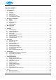
TABLE OF CONTENTS 1. Safety Regulations 7 1.1 General .......................................................................................................................................................................7 1.2 CH system...................................................................................................................................................................7 1.3 Gas system ...............................................................................................
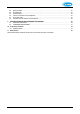
8.3 8.4 8.5 8.6 8.7 8.8 9. Burner resonates.......................................................................................................................................................46 No heating (CH) ........................................................................................................................................................46 Reduced output.................................................................................................................................
This manual Using this manual you can safely install and maintain this appliance. Carefully follow the instructions. In case of doubt, contact Atmos Heating Systems. Keep these instructions near the appliance.
Atmos Warranty – Short version 1. 2. 3. 4. 5. 6. Atmos Warranty is against any material, construction or operation faults that are found to be of original manufacturing origin. A full statement of the Atmos Warranty is available (www.atmos.uk.com or 01327 871990). Atmos boiler warranty is, subject to conditions; two years from date of invoice, or 12 months from date of installation; whichever is the later.
1. SAFETY REGULATIONS The appliance must be installed in accordance with the Gas Safety (Installation and Use) Regulations; October 1994. Failure to install appliances correctly could lead to prosecution. Atmos Heating Systems does not accept any liability for damage or injury caused by not (strictly) observing the current safety regulations and instructions, nor by negligence while installing the Atmos InterCombi wallmounted gas heater and any accompanying accessories.
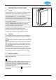
2. DESCRIPTION OF THE APPLIANCE 2.1 General The Atmos InterCombi wall-mounted gas boiler is designed for delivering heat to the water of a CH system and the domestic hot water. The air supply and flue discharge can be connected to the appliance by means of two separate pipes or a concentric connection. The appliance has its own wall mounting strip, but can also be fitted to an optional wall mounting frame that allows top connections.
Waiting position The LED of the on/off button and if necessary one of the LED’s of the domestic hot water Keep hot function are on. The appliance is ready for responding to the demand for CH or domestic hot water. 0 Pump overrun After the operation of the CH, the pump has an overrun. This overrun time is set to the value according to parameter 8 (see § 7.3; factory setting is 1 min). This setting can be changed. Note: If there is a hot water demand during this period, the overrun time is cancelled.
determined by the weather dependent control programmed in the controller. During CH operation, the demanded CH supply temperature is displayed on the operating panel. During CH operation, the actual CH supply temperature can be read by pressing the service button. Note: Instead of an on/off thermostat, an OpenTherm thermostat can be connected to the controller as described in §5.4.1. In this case, the desired CH temperature is set by the thermostat.
2.5 Test programmes In the controller, there is provision for putting the appliance into a test status. By activating a test programme, the appliance will become active with a fixed fan speed without intervention of the control functions. The safety functions remain active though. Simultaneously press + and – to switch off the test programme.
3.
3.1 Accessories Description Pipe mounting bracket • Connection supply and return 22 mm diameter • Connection cold and hot water 15 mm diameter • Connection gas ½" female thread • Mounting strip boiler • Bag with fixings Rear mounting frame for top pipe connection Bottom Pipework cover Outside sensor for weather compensation Conversion set to Propane (LPG or G31) Interface cable (for Installers) Part Ref 092.537 092507 092527 203.
4. INSTALLATION 4.
4.2 Unpacking the appliance 1. 2. Unpack the appliance. Check the content of the packaging. This consists of:• Appliance (A) • Mounting strip (B) • Condensate trap (C) • Installation Instructions • User Operating Instructions • Warranty card 3. Valve set (supplied separately with boiler) comprising 2 x 22mm isolation valves, 1 x 15mm isolation valve with blue lever (for cold water), 1 x gas valve. 4. Check the appliance for any damage: report damage to the Supplier immediately.
4.4 Boiler location Clearances Above casing 200mm min Below casing 230mm min RH 30mm min LH 30mm min (in operation) LH 140mm min (servicing) Front 30mm min (in operation) Front 450mm min (servicing) Keep 50 mm free space above the front panel in order to be able to remove the front panel from the casing. Allow 140 mm on the left side for swinging out the expansion vessel during commissioning/service. The appliance can be fitted to a mounting frame.
4.5 Mounting and General Information Depending on the mounting option ordered, the following mounting methods are available:Mounting strip (A) alone, OR mounting strip (A) and optional pipe mounting bracket (B), OR rear mounting frame (C) and pipe mounting bracket (B), which are both optional items. This arrangement allows for vertical pipework behind the boiler. Note that when the pipe mounting bracket is used, the pipes can be connected before installing the appliance. A 4.5.1 1. 2.
4.5.4 1. 2. 3. Installation connections Make the various connections to the valves (see diagram). Install a filling loop (not supplied) between the cold water inlet pipe and the CH return connection. For most installations, the flexible tube for the safety discharge will be long enough to fit into the condensate discharge waste pipe (see below). In cases where this does not apply, install a 15 mm copper safety discharge pipe to fit into the waste pipe (as shown in the diagram, §5.
4.8 Condensate disposal The appliance is provided with a 25 mm flexible pipe from its condensate trap. As given in §4.6, this should be inserted into an open waste pipe of not less than 32 mm diameter, together with the safety discharge pipe.
5. CONNECTIONS 5.1 Connect the CH system 1. 2. Flush the CH system thoroughly. Mount the flow and return pipes to the mounting bracket. All pipes must be mounted tension-free in order to avoid ticking of the pipes. Existing connections must not be twisted in order to avoid leaks at the connections with the external pipes. The CH system should be provided with:• A filling loop in the return pipe directly below the appliance. • A drain tap at the lowest point of the system.
5.1.4 Underfloor heating For a good operation of the domestic hot water supply, there must be no undesired circulation through the appliance caused by a second pump of the CH circuit. Connect underfloor heating with an electric shut-off valve (two-way valve) to prevent circulation through the appliance when there is no demand for central heating. A. Boiler B. Pump C. Thermostatic control valve (Note: Valve for underfloor heating has remote sensor) D. Spring-operated non-return valve E.
5.3 1. 2. 3. 4. 5. 5.4 Connecting the gas supply Connect the appliance gas valve to the gas pipe. Check the boiler's data plate to ensure that the appliance has been set for the correct gas supply. The boiler is supplied for Natural Gas (G20). A propane (G31) gas conversion set is available and an appropriate sticker is included (see §7.7). The meter governor should deliver a dynamic pressure of 20mbar for natural gas or 37mbar for propane.
Controller Label and Associated Terminals Note: Terminals X4/11 & 12 are available for OpenTherm modulating stat. 5.4.1 24V dc Electrical connections 24V dc Terminals X4 Description Room stat Outside temp sensor OpenTherm modulating stat Frost stat Connector X4 6-7 8-9 Remarks 6= +24Vdc 11 - 12 Remove link 4-5 & 6 - 7 not used Parallel through room stat Power 24Vdc (3VA) 6= +24Vdc, 9= -. 6 -7 Notes 1. Under no circumstances must any electrical power be input to the room thermostat terminals.
5.4.3 Outside temperature sensor (Weather compensation option) The appliance has a connection for an outside temperature sensor. The outside temperature sensor can be applied in combination with an on/off room thermostat or time clock. If not using either of these, a wire link must be made across X4/6 & 7 (or X2/1 & 3) to give continuous operation. Preferably, the outside sensor should be mounted on a North facing wall.
5.5 General Flue Requirements 5.5.1 Flue terminal clearances The flue terminal must be sited with minimum clearance distances as shown in the diagram. A terminal guard must be fitted if the terminal is sited less than 2m above ground level, or above a balcony, or accessible flat roof.
Note regarding internal air-flue systems. It is recommended that the boiler is sited on or next to an external wall so as to negate the need to use a void or enclosure as a route for the flue system. Where this is not possible the following applies: CORGI have issued a Guidance Document on the safe installation of flue systems within a dwelling. This is a Technical Bulletin reference TB200, and can be downloaded from the internet.
Mounting 60/100mm horizontal concentric terminal 1. Drill hole of diameter 110 mm or larger hole. 2. Cut the terminal to the length required. 3. Slide the terminal into the opening and fit rosettes to cover the opening. 4. Ensure the pipes slope back to the appliance. An alternative telescopic 60/100 horizontal concentric terminal is available from Atmos. The flue should be adjusted to length and the supplied sealing tape applied.
5.6.3 Vertical Concentric connection Straight adapters are available for either 60/100mm or 80/125mm systems. IMPORTANT! Using the concentric adapter set (see photo), the standard two-pipe connection can be changed into a concentric connection. 1. Seal the open air supply connections in the appliance with the sealing cap delivered with the set (item C in photo). 2. Remove the sealing ring around the flue discharge in the appliance, as shown above. 3.
80/125mm Concentric extension for balcony outlet When the free outlet is hindered by an eave, balcony, gallery or anything else, the concentric terminal must be extended to at least the front side of the overhanging part (see diagram).
5.6.6 80mm twin pipe flue system Refer to the Atmos Price List for the full list of flue components. Terminal The flue discharge at the terminal must be at least 75mm in front of the air intake and the distance between the two pipes at least 75mm. 80mm Twin pipe extensions for balcony outlet When the free outlet is hindered by an eave, balcony, gallery or anything else, the air supply pipe and the flue discharge pipe must be extended to at least the front side of the overhanging part.
5.6.7 Plastic twin pipe flue systems NOTE Consult Atmos for these systems. Use of non-approved flue systems will invalidate the guarantee. For special applications, the appliance can be used with plastic flue pipes, which are available from Atmos as follows: PPS. This is a rigid translucent plastic pipe in 60mm and 80mm diameters, together with a range of fittings. This is suitable for continuous use at 120ºC and is therefore suitable for connection from the appliance to the flue terminal.
5.7 Roof outlet prefabricated chimney Appliance category: C33 When there is little space in a shaft, a roof outlet through a prefabricated chimney may be necessary. The prefabricated chimney must comply with the minimum lengths shown. The supplier must guarantee the proper operation of the prefabricated chimney with respect to wind attack, ice formation, rain ingress, etc.
5.8 Atmos MS System Appliance category: C53 (individual vertical flue and separate horizontal air inlet). CAUTION The air supply (A) in the outside wall must be provided with an Atmos inlet grid. Flue terminals (B) can be individual, or common terminals can be provided for groups of up to 6 flues. Maximum pipe length See §5.6.5. The air supply pipes and flue discharge pipes should be 80mm. Mounting of air supply - horizontal The air supply (A) can be made at any place in the outside wall. 3.
5.9 Atmos Communal Flue System (CFS) A design service is provided for each application. There are different configurations possible and the main ones are illustrated. CFS-NV Naturally ventilated, working under negative pressure CFS-FA Fan assisted, working under positive pressure – smaller diameter pipes are used 5.9.
6. COMMISSIONING 6.1 Fill and de-aerate the appliance and the system WARNING Connect the appliance to the mains voltage only after filling and de-aerating! 6.1.1 CH system WARNING All new and existing systems must be thoroughly drained and flushed out in accordance with BS7593 requirements. A suitable cleaning agent is Sentinel X400, following the manufacturer’s instructions. A corrosion inhibitor should be added and the concentration level checked.
6.2 Commissioning of the appliance After having carried out the above operations, the appliance can be commissioned. 1. Switch on the electrical supply to the appliance. The appliance may carry out a self-test as determined by the controller: 2 (on service display). After completing the self-test, a horizontal mark will appear in the service display: - . 2. Press the on/off button in order to put the appliance into operation. The boiler is heated and on the service display appear 3 , 4 , 7 . 3.
6.3 System Shutdown CAUTION Drain the appliance and the system when the mains voltage has been disconnected and there is a chance of freezing. 1. 2. 3. 4. Drain the appliance using the drain tap. Drain the system at the lowest point. Close the main valve for the cold water supply to the boiler. Drain the appliance by disconnecting the domestic hot water connections underneath the appliance or opening hot water taps. 6.3.
7. SETTING AND ADJUSTMENT The functioning of the appliance is mainly determined by the (parameter) setting in the appliance controller. A part of this can be set directly via the operating panel, while another part requires an Installer code to be entered before settings can be changed. 7.1 Directly via operating panel The following settings can be made directly via the operating panel. Appliance on/off The appliance is activated by means of the On/Off button.
7.3 Parameters Parameter 0 Service code [15] Factory setting InterCombi HE 32 - 1 System type 0 2 CH pump continuous 0 3 Set CH power 50 4 5 Set HW power Min. supply temperature of the control line Min. outside temperature of the control line Max.
7.4 Setting maximum CH power The maximum CH power is set to 50% in the factory. When the CH system requires more or less power, the maximum CH power can be changed by adjusting the fan speed. See table: Setting CH power. This table gives the relation between the fan speed and the appliance power. Setting CH power Required CH power InterCombi HE32 (approx kW) 26.2 23.5 21.9 20.4 18.9 17.4 15.8 14.2 12.7 11.1 9.5 8.
7.6 Weather-dependent control T supply °C When the outside sensor is connected, the supply temperature is automatically controlled dependent on the outside temperature in accordance with the set control line. The T set CH (= CH supply temperature) is set via the temperature display. If required, the control line can be adjusted by the service code. See § 7.3. X. Y. A. B. T outside °C T supply °C factory setting example 7.
In case of any alterations, replacement of the gas valve or conversion to another gas type, the control must be checked and reset if necessary according to the table below:Gas type Natural gas H Gas category 2H G20 CO2% at low position (L) 8.8 – 9.2 (service and -) CO2% at high position (H) 8.6 – 9.6 (service and +) Gas inlet pressure dynamic (mBar) 17-25 Gas inlet pressure static (mBar) 20 Gas setting ring diameter (mm) 6.95 Minimum speed (% of max) 30 (parameter d) Min.
13. Exit the test mode by simultaneously pressing the “+” and “–“ buttons on the operating panel. Replace the dust cap (A) and close the flue gas measuring nipple. 14. Remount the front cover of the appliance. Caution: Check the measuring nipples used for gas tightness.
8. FAULTS When the controller detects a fault, the red fault LED flashes (above the Reset button) and a fault code is shown on the Temperature display. After the fault has been remedied, the controller can be restarted by pressing the Reset button for 5 secs.
8.1 Burner does not ignite Possible causes Remedies Gas tap is closed Yes 1. Open the gas tap. No Air in the gas pipe. Yes 1. De-aerate the gas pipe. No Inlet pressure too low. Yes 1. Contact the gas company. No No ignition Yes 1. Replace the ignition probe. No No spark. Ignition unit on gas unit faulty 1. Check the cabling. Yes 2. Check the spark probe 3. Replace the ignition unit. No Gas-air control not adjusted properly. Yes 1. Check the adjustment, see Gas-air control. No Fan faulty 1.
8.3 Burner resonates Possible causes Remedies Inlet pressure too low. Yes 1. The house gas meter may be faulty. Contact the gas company. No Re-circulation of the flue gases. No Gas-air mixture not adjusted properly. 8.4 Yes 1. Check the flue gases and air supply. Yes 1. Check the adjustment, see Gas-air control. No heating (CH) Possible causes Remedies Room thermostat/weather-dependent control not closed or faulty. 1. Check the wiring. Yes 2. Replace the thermostat. 3.
8.5 Reduced output Possible causes Remedies At high speed, the power has decreased by not more than 5%. 8.6 Yes 1. Check appliance and flue system for pollution. 2. Clean appliance and flue system. CH does not reach the correct temperature Possible causes Remedies Room thermostat settings not correct. Yes 1. Check the setting and adjust if necessary: set to 0.1 A. Yes 1. Raise the CH temperature, see CH operation. 2. Check the outside sensor for short circuit: remedy this.. Yes 1.
8.8 Hot water does not reach the correct temperature Possible causes Remedies Tap flow higher than 9 l/min. Yes 1. Adjust the inlet combination. No Temperature setting water circuit too low. Yes 1. Set the hot water circuit to 60ºC, dependent on the required temperature. No No heat transfer due to scaling or pollution in the heat exchanger on the tap water side. No Yes 1. Descale or flush the heat exchanger on the tap water side. Cold water temperature < 10ºC. Yes 1. Table 6.
9. SERVICING THE BOILER AND COMPONENT REPLACEMENT 9.1 SERVICING THE BOILER The appliance and the system should be serviced annually by a qualified service engineer. For appliances connected to propane gas, a six monthly service in the first two years to simply clean the condensate trap and pipe may be neccessary. Due to the nature of propane gas, a jelly like substance can build up in the trap, causing it to become blocked. 9.1.
Open the gas tap and check the gas couplings below the gas valve and on the mounting bracket for leaks. Switch on the electrical supply to the appliance Switch on the appliance, using the On/Off button on the operating panel. Check the front cover and the connection of the fan to the front cover for leaks. 9.1.3 Note for CFS systems with Non Return Valve (flue gas) When refitting the fan, the NRV MUST be refitted (see diagram). Fold the silicon valve (1) of the NRV carefully into a U-form.
9.2 COMPONENT REPLACEMENT 9.2.1 Preparation Switch off the appliance using the On/Off button on the operating panel. Switch off the electrical supply to the appliance. Close the gas tap. Unscrew the two recessed screws left and right at the front underneath the appliance and lift/remove the front panel. See photo in § 4.4.3. Wait until the appliance and the burner have cooled down.
9.2.5 Burner/ spark ignition probe Remove the front cover of the heat exchanger as described in § 9.1.2. Unscrew the 4 screws shown on the photo to allow the stainless steel burner mesh to be removed. These screws are Torx 20 (RVS A2 4,2x25”) or Allen bolt M4x20 (units before 2006). The burner gasket should be checked and replaced if damaged. Replace the burner mesh assembly and refit the screws. The spark ignition probe is shown in the photo in § 9.1.2 and also the diagram in § 8.2.
9.2.11 Pump head Disconnect the pump wires from the controller (see note in § 9.2.1). Undo two Allen bolts on the Wilo pump head (alternative pump Grundfos has 4 Allen bolts) to remove the pump head from the body. Fit replacement pump head in reverse order. The pump must be vented via its vent plug after refilling the appliance. 9.2.12 Expansion vessel Unscrew the flexible hose connection, making sure that the sealing ring is not damaged.
10. TECHNICAL SPECIFICATIONS Appliance category Gas inlet pressure Suitable for gas B13; B33; C13; C 33; C 43; C53; C63; C83 20 mbar II2 H3P Technical data InterCombi HE 32 Domestic hot water Heat power input (gross) Heat power input (net) Heat output Domestic hot water threshold Domestic hot water flow rate 60°C (∆T=50°C) Domestic hot water flow rate 45°C (∆T=35°C) Domestic hot water flow rate 40°C (∆T=30°C) Max. domestic hot water temperature setting Max.
10.1 Notes 1. 2. 3. 4. Electrical diagram F1: 5x20mm anti-surge fuse 2A. 230Vac stat circuit: Available for room stat, etc. The switched live can also be used for S plan or Y plan circuits (note that the 230Vac live to the Wiring Centre must come from the same fused spur as the 230Vac supply to the boiler). OpenTherm: When using an OpenTherm thermostat, the link 4 – 5 must be removed, and 6 – 7 not used. For systems requiring an external hot water On/Off switch, please consult Atmos.
11. CE DECLARATION Declaration of conformity according to ISO IEC GUIDE 22.
881617_Inst_InterCombiHE32 57