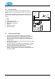
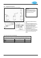
5.1.4 Under floor heating For a good operation of the domestic hot water supply, there must be no undesired circulation through the appliance caused by a second pump of the CH circuit. Connect under floor heating with an electric shut-off valve (two-way valve) to prevent circulation through the appliance when there is no demand for central heating. A. B. C. D. E. F. G. H. 5.2 1. 2. 3. 4. 5.
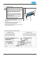
5.3 Electrical connection CAUTION The appliance requires a 230 V ac 50 Hz mains supply, and must be earthed and connected via a double pole isolating switch fitted with a 3 amp fuse. The switch must be readily accessible, within 1m of the appliance, and provide complete electrical isolation for the boiler and control system. The appliance is supplied factory wired complete with 1 m of mains cable. All electrical connections to the mains supply must be made in full accordance with the current I.E.E.
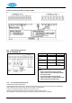
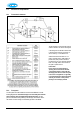
Controller Label and Associated Terminals for HE40C 5.3.1 4V dc Electrical connections 24V dc Terminals X4 Description Room stat Outside temp sensor OpenTherm modulating stat Frost stat Connector X4 6-7 8-9 Remarks 6 = + 24Vdc 11 - 12 6 - 7 not used 6 -7 Parallel through room stat Power 24Vdc (3VA) 6 = + 24Vdc, 9 = -. Notes 1. Under no circumstances must any electrical 2. 5.3.2 power be input to the room thermostat terminals. It is a volt-free switch.
5.3.3 Outside temperature sensor (Weather compensation option) The appliance has a connection for an outside temperature sensor. The outside temperature sensor can be applied in combination with an on/off room thermostat or time clock. If not using either of these, a wire link must be made across X4/6 & 7 (or X2/1 & 3) to give continuous operation. Preferably, the outside sensor should be mounted on a North facing wall.
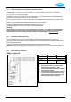
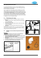
.4 General Flue Requirements 5.4.1 Flue terminal clearances The flue terminal must be sited with minimum clearance distances as shown in the diagram. A terminal guard must be fitted if the terminal is sited less than 2m above ground level, or above a balcony, or accessible flat roof.
Note regarding internal air-flue systems. It is recommended that the boiler is sited on or next to an external wall so as to negate the need to use a void or enclosure as a route for the flue system. Where this is not possible the following applies: There is a Guidance Document available on the safe installation of flue systems within a dwelling. This is a Technical Bulletin reference TB 008 (Edition 2) and is available from Gas Safe Registers website.
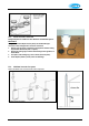
6. 7. 8. 9. Mounting 60/100mm horizontal concentric terminal Drill a hole of 110 mm diameter or larger. Cut the terminal to the length required. Slide the terminal into the opening and fit rosettes to cover the opening. Ensure the flue pipe slopes back to the appliance. An alternative telescopic 60/100 horizontal concentric terminal is available from Atmos. The flue should be adjusted to length and the supplied sealing tape applied.
5.5.3 Vertical Concentric connection Straight adapters are available for either 60/100mm or 80/125mm systems. IMPORTANT! Using the concentric adapter set (see photo), the standard two-pipe connection can be changed into a concentric connection. 1. Seal the open air supply connections in the appliance with the sealing cap delivered with the set (item C in photo). 2. Remove the sealing ring around the flue discharge in the appliance, as shown above. 3.
80/125mm Concentric extension for balcony outlet When the free outlet is hindered by an eave, balcony, gallery or anything else, the concentric terminal must be extended to at least the front side of the overhanging part (see diagram).
5.5.6 80mm twin pipe flue system Refer to the Atmos Price List for the full list of flue components. Terminal The flue discharge at the terminal must be at least 75mm in front of the air intake and the distance between the two pipes at least 75mm. 80mm Twin pipe extensions for balcony outlet When the free outlet is hindered by an eave, balcony, gallery or anything else, the air supply pipe and the flue discharge pipe must be extended to at least the front side of the overhanging part.
5.5.7 Plastic twin pipe flue systems NOTE Consult Atmos for these systems. Use of non-approved flue systems will invalidate the guarantee. For special applications, the appliance can be used with plastic flue pipes, which are available from Atmos as follows: PPS. This is a rigid translucent plastic pipe in 60mm and 80mm diameters, together with a range of fittings. This is suitable for continuous use at 120ºC and is therefore suitable for connection from the appliance to the flue terminal.
5.6 Roof outlet prefabricated chimney Appliance category: C33 When there is little space in a shaft, a roof outlet through a prefabricated chimney may be necessary. The prefabricated chimney must comply with the minimum lengths shown. The supplier must guarantee the proper operation of the prefabricated chimney with respect to wind attack, ice formation, rain ingress, etc.
5.7 Atmos MS System Appliance category: C53 (individual vertical flue and separate horizontal air inlet). CAUTION The air supply (A) in the outside wall must be provided with an Atmos inlet grid. Flue terminals (B) can be individual, or common terminals can be provided for groups of up to 6 flues. Maximum pipe length See §5.5.6. The air supply pipes and flue discharge pipes should be 80mm. Mounting of air supply - horizontal The air supply (A) can be made at any place in the outside wall. 1.
5.8 Atmos Communal Flue System (CFS) A design service is provided for each application. There are different configurations possible and the main ones are illustrated. CFS-NV Naturally ventilated, working under negative pressure CFS-FA Fan assisted, working under positive pressure – smaller diameter pipes are used 5.8.
6. COMMISSIONING 6.1 Fill and de-aerate the appliance and the system WARNING Connect the appliance to the mains voltage only after filling and de-aerating! 6.1.1 CH system WARNING All new and existing systems must be thoroughly drained and flushed out in accordance with BS7593 requirements. A suitable cleaning agent is Sentinel X400. A corrosion inhibitor should be added and the concentration level checked.
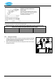
6.2 Commissioning of the appliance After having carried out the above operations, the appliance can be commissioned. 1. Switch on the electrical supply to the appliance. The appliance may carry out a self-test as determined by the controller: 2 (on service display). After completing the self-test, a horizontal mark will appear in the service display: - . 2. Press the on/off button in order to put the appliance into operation. The boiler is heated and on the service display appear 3 , 4 , 7 . 3.
Remarks The appliance has been provided with an electronic controller that ignites the flame and continuously monitors this at each heat demand from the heating system. The circulation pump starts running at each heat demand of the boiler. The pump has an overrun time of 1 minute. The overrun time can be changed if necessary. See Installer settings. The controller will automatically run the pump for 10 seconds, once every 24 hours, to prevent it from getting stuck.
7. SETTING AND ADJUSTMENT The functioning of the appliance is mainly determined by the (parameter) setting in the appliance controller. A part of this can be set directly via the operating panel, while another part requires an Installer code to be entered before settings can be changed. 7.1 Directly via operating panel The following settings can be made directly via the operating panel. Appliance on/off The appliance is activated by means of the On/Off button.
7.3 Parameters Par. Setting 0 Service code [15] 1 System type 2 CH pump continuous 3 Set CH power 4 5 A Set max power Min. supply temperature of the control line Min. outside temperature of the control line Max. outside temperature of the control line CH pump overrun time after CH operation CH pump overrun time after external HW tank operation Position of three-way or two-way valve b 6 Factory setting Description InterSystem HE 26 HE 40C Access to installer settings.
7.4 Setting maximum CH power The maximum CH power is set to 50% (for HE26) or 99% (for HE40C) in the factory. When the CH system requires more or less power, the maximum CH power can be changed by adjusting the fan speed. See table parameter 3, set CH power. This table gives the relation between the fan speed and the appliance power. Setting CH power Required CH power (approx kW) HE26 HE 40C 26.2 23.5 21.9 18.9 15.8 12.7 9.