
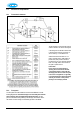
Technical data


24
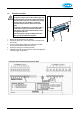
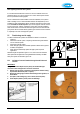
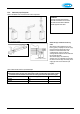
5.3.3 Outside temperature sensor (Weather compensation option)
The appliance has a connection for an outside temperature sensor. The outside temperature sensor can be applied in
combination with an on/off room thermostat or time clock. If not using either of these, a wire link must be made across X4/6
& 7 (or X2/1 & 3) to give continuous operation.
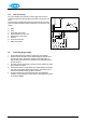
Preferably, the outside sensor should be mounted on a North facing wall. It should not be located where it might be affected
by (the warmth of) sun light, chimneys, air vents or an open window.
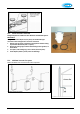
To avoid problems with moisture, the sensor should be placed with the cable outlet downwards and the cable looped so that
the lowest part of the cable is lower than the hole in the wall. Run the cable back to the appliance, ensuring that holes in
walls are sealed, and pass through a suitable cable gland in the bottom of the appliance.
Connect the outside temperature sensor cable to the controller as shown in §5.3.1.
See Weather-dependent control §7.6 for the setting of the CH temperature line.
WARNING!
When the boiler is also used to heat a hot water storage tank it is necessary to put in place in arrangement whereby
the boiler is delivering a higher flow temperature whenever there is a call for heat for hot water. Contact Atmos for
further information or consult Technical Data Sheets TDS003 and TDS010 available on www.atmos.co.uk.
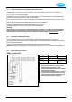
5.3.4 OpenTherm modulating thermostat
The appliance is suitable for connecting an OpenTherm modulating thermostat as shown in §5.3.1.
The most important function of the modulating thermostat is calculating the supply temperature at a required room
temperature in order to make optimum use of the modulating function. With every heat demand, the appliance display shows
the required supply temperature.
The manual supplied with the OpenThern thermostat should be consulted for more information.
NOTE! When connecting an OpenTherm modulating thermostat to a boiler that is also used to heat a hot water storage tank,
please contact Atmos for wiring instructions or consult Technical Data Sheet TDS009 available on www.atmos.co.uk.
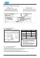
5.3.5 230Vac Electrical connections
230Vac Terminals X2
Description
Connector X2
Remarks
Mains In
L= 2, N= 4
Earth:see
§10.1
Room stat
1= switch live, 3= live (fus
ed)
Frost stat
1
-
3
Parallel through
room stat
Notes
1. The 230Vac stat circuits are alternative to the
24Vdc circuits. If the stat has a neutral
connection for heat accelerator, then connect it
for more efficient operation.
2. The switched live can also be used for S plan or
Y plan circuits (note that the 230Vac live to the
Wiring Centre must come from the same fused
spur as the 230Vac supply to the boiler).