
Quick Start Guide


Atomos Shogun Studio 2 - Quick Start Guide | 3
Media
Widely available 2.5” SSDs are the basic storage media for Atomos 4K
Monitor Recorders. We work closely with leading drive manufacturers to
qualify as many options as possible. SSDs are required for 4K recording
and for more demanding production environments that may not be suited
to spinning hard disks.
We have worked closely with leading media manufacturers to develop media
designed specically for the Atomos Ninja V, that with the addition of AtomX
SSDmini handles is 100% compatible with Shogun Studio 2. The AtomX
SSDmini is smaller than a standard SSD, but utilises the same SATA connection
as normal HDD/SSD media and is compatible with all Atomos recorders and
docking stations. AtomX SSDmini (with SSDmini Handle) ts directly into
the Shogun Studio 2 disk slot without the need for a Master Caddy II.
For more information about supported drives and accessories, visit:
www.atomos.com/drives
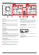
Assemble the Master Caddy
Position a Solid State Drive (SSD) into the Master Caddy. Assemble
completely and align screw holes on all three pieces. Insert screws last. Do
not over-tighten. For more detailed instructions please download the full
Shogun Studio 2 User Manual.
Handle SSD with care
Avoid contact with circuit board and connectors. Refer to media
manufacturer’s manual for handling instructions.
Format SSD
With your chosen SSD inserted in to the Master Caddy or SSDmini with
attached handle insert the drive into the channel you would like to operate.
Note each drive slot corresponds to the monitor it is located beneath.
With the drive inserted you can touch the drive icon in the top right of the
touch screen interface. Select to the format option to erase and prepare
the drive for use. For drives that support secure erase an option will be
available for this. It will take slightly longer to perform the format process
and SSD will be reset to factory settings.
Important: Never remove the SSD whilst recording as this may cause
data corruption.
Connect and power-up
We recommend that you connect Shogun Studio 2 directly to a reliable
connection or via a power distribution unit / strip to an interruptible power
supply in your rack. The Shogun Studio has 2 x AC inputs and we advise
using both where possible.
Connecting Power-up and about PSUs
The rear bottom left hand side of the unit are located AC1 and AC2 inputs
with IEC C14 sockets (see next page). Connect the provided power cables
to the sockets and then connect to main power. The dual power supplies
internally balance the power draw across both units and additionally allows
for backup power if one of the power supplies fail. If a PSU does fail a
warning screen will be displayed. To continue using the unit, activate single
power supply mode by clicking OK. Once connected press the power button
on the front of the unit and both recorder channels will power up.
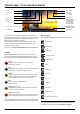
Connection layout
Looking at Shogun Studio 2 from the front, recorder channel 1 is on the
left and recorder channel 2 is on the right. The rear panel has been laid
out symmetrically to match what you see on the front. The major sections,
recorder channel 1/control & updates/recorder channel 2, contain all of the
in/ out connections relevant to that section.
The Connections of the Shogun Studio2
Video: Each recorder Channel has 2 x 3G and 2 X 12G SDI inputs, and 1
x 12G SDI output, with the option to have a 2nd 12G SDI output when in
playback mode. The 12G SDI are also backwards compatible to 6G, 3G,
1.5G SDI and can be used for dual or quadlink to use with your existing
equipment. Each recorder Channel also has a HDMI connection for input
and output. These are both 2.0 specication to handle 4K video up to
60fps, allowing 10-bit video in and out.
Audio: Each recorder channel has 2 x XLR inputs and 2 x XLR outputs.
These can be used at Line, Mic and Pro level, which can be dened
by the Audio menu. The inputs can also provide 48V Phantom power to
compatible microphones.
Synchronization: Each Recorder channel has Genlock input and output
via BNC as well as LTC time code input and output. Operation of LTC can
be found in the Timecode menu & operation of Genlock found in the output
sections of the device menus. LTC can be activated whilst in Record mode
and Genlock is available whilst in playback mode.
RS422 9pin D-Sub: Each recorder has it’s own dedicated 9pin D-Sub with
RS422 machine control. Simply connect your RS422 cable from your device
or controller and Shogun Studio 2 will receive and action the commands.
Please refer to the Shogun Studio 2 User Manual for a list of supported
RS422 commands and qualied controllers at www.atomos.com/support
USB: The USB connection on the rear is for SERVICE ONLY and should
only be used if instructed to do so as part of rmware updates.
Headphone Monitoring Jack: On the front of the unit, each recorder
channel has it’s own individual 3.5mm jack for audio monitoring. The
channels to be monitored can be selected via the audio menu on the
Shogun Studio 2 touchscreen.
Calibration Socket: Between the monitors of the recorder channels is
a 2.5mm mini jack. This is for use with the optional x-rite i1 display pro
calibrator and Atomos Calibration software. The single socket is able
to calibrate both screens. Connect the x-rite unit, open the calibration
software and select device 1 in the software to calibrate Recorder Channel
1 or select device 2 to calibrate Recorder Channel 2.
Control: Each of the Shogun Studio channels can be operated via the
independent touch screens to adjust record, monitor, playback and edit
functions. Please refer to the manual for further details.
Touch Screen interface: Pictured on page 6 are the main controls seen
when the Shogun Studio 2 is powered on with video input connection
present and recording media in the drive bay. Touch these items to access
or cycle through the available options. For example, touching the Video
Input Format will open the Settings menu panel and jump directly to the
related Input settings.
Power Button: A single power button is used to turn both devices on and off.
A simple tap of the power button will also lock or unlock the touch interface of
both recorder channels. A long press (4 seconds) will turn both units off.
Record Button
Positioned in the lower centre of the front panel is a record button. Pressing
this will trigger both channel to begin recording based on current settings.
To stop recording, press and hold until recording has stopped.
Connect and power-up cont.