ABLE Pick Pick-to-light (AT705-23-3K-RF) User Manual V 1.0 Updated at: 2011/12/01 by ATOP Technologies, Inc. Tel: +886-3-5508137 Fax: +886-3-5508131 E-mail: abelin@atop.com.
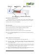
Introduction ABLEPick is an advanced paperless picking system providing an innovative, streamlined and cost-effective Pick-to-light solution to simplify the order fulfillment process in warehouse or distribution center. ABLEPick use a state-of-the-art and light-directed technology to maximize the picking productivity, speed and accuracy in different picking operation. Products Features - Ethernet architecture, follow up the standard TCP/IP communication protocol. - CABLELESS pick tags.
. PICK-TO-LIGHT OPERATION Work flow of pick-to-light system: Below simply describe the basic operation Data entry Picking list files can be downloaded to the LAN server or PC from WMS/MIS host. These files will be read and merged into pick-to-light picking list database. Control and communication Pick-to-light software will monitor picking flow and offer real-time information on the screen.
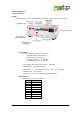
ABLEPick Hardware TCP/IP controller AT500 TCP/IP controller is a data transmission medium between picking control PC and all the picking devices. Which is Ethernet architecture product, following up the standard TCP/IP communication protocol to communicate with the host PC. Each controller has 4 output channels to connect to the picking devices, each channel can connect to maximum 30 devices. So one TCP/IP controller can connect to maximum 120 pcs of picking devices.
I/O port pin assignment pin Defin. 1 RTS+ 2 RTS3 DATA+ 4 DATA5 GND 6 +12V /3A 7 Fan switch, 45 C auto power on 8 AT500’s IP configuration AT500’s default IP address is “10.0.50.100” and sub-mask is “255.255.0.0”. You can use ATOP’s tool “MONITOR.exe” to know and re-configure each AT500’s IP address. Connection to TCP/IP controller (AT500) Since AT500 has no DHCP function, so its host control PC/NB need to assign one IP address which have to be within the same domain as the AT500.
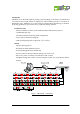
Picking Tag : AT705-23-3K-RF Federal Communication Commission Interference Statement This equipment has been tested and found to comply with the limits for a Class B digital device, pursuant to Part 15 of the FCC Rules. These limits are designed to provide reasonable protection against harmful interference in a residential installation.
Large illuminated confirmation button. confirmation button has 6 colors LED design, which are RED, GREEN, AMBER, BLUE, PURPLE and INDIGO individually. The default color is RED. LED’s color can be configured by software, which can be stored in the EEPROM. Power on procedure Step1: The 7-segment will show “8“ from 1st digit to last digit sequentially(from right to left). Step2: The LED light will change color: RED, GREEN and AMBER sequentially. Step3: Show the F/W version of the tag. For example: “U1.2”.
Self-test function enabled Step1: Press the “up-count” button, then “Confirmation Button” at the same time. 7-segment LED display will show the address ID of the tag. For example: “[001]”. However, there is no digit is blinking which is different from the address configured procedure. Step2: Press the “Confirmation button”. The 7-segment LED display will show the baud rate of the tag. For example: “57600” is 57600 bps. The tag will detect the baud rate of the host and configure itself automatically.