
User's Manual


ABLEPick pick-to-light user manual
6
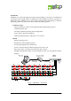
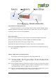
Large illuminated confirmation button.
confirmation button has 6 colors LED design, which are RED, GREEN, AMBER, BLUE,
PURPLE and INDIGO individually. The default color is RED. LED’s color can be configured
by software, which can be stored in the EEPROM.
Power on procedure
Step1: The 7-segment will show “8“ from 1st digit to last digit sequentially(from right to left).
Step2: The LED light will change color: RED, GREEN and AMBER sequentially.
Step3: Show the F/W version of the tag. For example: “U1.2”.
Step4: Show the address ID of the tag. For example: “[001]” (this is a decimal number).
Step5: Show the function configuration of the tag. The default function configuration value is
115. in decimal.
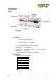
Address configuration via the buttons directly.
In a field bus, each Picking Tag must be with unique address ID.
Step1: Press the “up-count” and “down count” button at the same time, then push the
“Confirmation Button”. Then 7-segment LED display will show the address ID of the
tag. For example: “[001]”.
Step2: The 1st changeable digit will be blinking. Using the“up-count” and “down count” button
to adjust the digit to the adequate value. Or using the “Confirmation button” to switch to
next changeable digit. There are 3 digits been able to be changed.
Step3: Press the “Confirmation Button” many times to exit the address configuration. Once the
display is off, it means the node address configuration is completed.