
User Manual


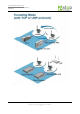
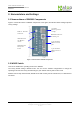

Table Of Contents

User manual Version 1.0
ABLELink
Wireless Serial Server
SW2001
Copyright © 2006 Atop Technologies, Inc.
All rights reserved. Designed in Taiwan.
8 / 51
2. Nomenclature and Settings
2.1 Nomenclature of SW2001 Components
Figure 2.1 shows the names of SW2001 components. In the figure, the indicated switch settings represent
factory settings.
10/100M
Ethernet port for
settings
Mini-DIN Connector
for Serial port
5-pin Terminal
Block for Serial
port
3-pin Terminal
Block for Power
input
SMA rev. Antenna
Connector
LED indication
for Wireless
Status
LED indication
for System
Status
Figure 2.1. Nomenclature of SW2001 Components
2.2 MODE Switch
This sets or initializes the operating mode for the SW2001.
The factory default setting is RS-232 mode. You can use the software configurations to change the
operating mode from the factory default settings to your desired mode by web or telnet tools.
SW2001 can be setup either RS-232, RS-485 or RS-422 mode by remote network tools, ex. Web browser
and telnet.