EH7510 Industrial Managed Ethernet Switch User Manual Version 1.0 October, 2011 TEL: +886-3-5508137 FAX: +886-3-5508131 http://www.atop.com.
Atop Industrial Managed Ethernet Switch EH7510 User Manual V 1.0 Important Announcement The information contained in this document is the property of Atop Technologies, Inc. and is supplied for the sole purpose of operation and maintenance of Atop Technologies, Inc products.
Atop Industrial Managed Ethernet Switch EH7510 User Manual V 1.0 Table of Contents Preface ........................................................................ 1 Chapter 1: Introduction ................................................ 2 1.1 What is a Managed Industrial Switch ........................................... 2 1.2 Software Features ....................................................................... 3 1.3 Hardware Features .................................................................
Atop Industrial Managed Ethernet Switch EH7510 User Manual V 1.0 2.5.1 LACP .................................................................................... 29 2.5.2 Trunking ................................................................................ 30 2.6 Unicast/Multicast MAC ............................................................... 31 2.6.1 MAC Address Table .............................................................. 32 2.6.2 Add Uni/Multicast MAC .....................................
Atop Industrial Managed Ethernet Switch EH7510 User Manual V 1.0 2.13.2 ERPS .................................................................................. 67 2.13.2.1 UERPS Settings (optional) ............................................. 71 2.13.3 iA-Ring ................................................................................ 73 2.13.4 Compatible-Ring ................................................................. 75 2.13.5 U-Ring ...........................................................
Atop Industrial Managed Ethernet Switch EH7510 User Manual V 1.0 Glossary ...................................................................
Atop Industrial Managed Ethernet Switch EH7510 User Manual V 1.0 Preface This manual contains some advanced network management knowledge, instructions, examples, guidelines, and general theories; designed to help users manage EH7510 and use its software, a background in general theory is a must when reading it. Please refer to the Glossary for technical terms and abbreviations.
Atop Industrial Managed Ethernet Switch EH7510 User Manual V 1.0 Chapter 1: Introduction 1.1 What is a Managed Industrial Switch Atop’s EH (Ethernet Switching Hub) 7510 is a powerful managed industrial switch; a switch is referred to as an OSI Layer 2* bridging device. Unlike an “unmanaged” switch, which is normally found in homes or in SOHO environments and runs in “auto-negotiation” mode, each port on a “managed switch” can be configured for its link bandwidth, priority, security, and duplex settings.
Atop Industrial Managed Ethernet Switch EH7510 User Manual V 1.0 1.
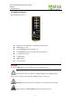
Atop Industrial Managed Ethernet Switch EH7510 User Manual V 1.0 1.3 Hardware Features Device Appearance, Fig. 1.1: Fig. 1.1 Dimensions: 53.4 mm (W) x 119.9 mm (D) x 145.7 mm (H) Weight: approx 1.1kg 8 x 10/100M Ethernet ports (Port # 1~8) 2 x Gigabit Ethernet ports or 2 x Fiber ports (Port # 9~10) 1 x Serial Console Port 1x4 DIP switch LED indicators 1 x Reset button Caution An approved Optical transceiver should be chosen to plug into the slot.
Atop Industrial Managed Ethernet Switch EH7510 User Manual V 1.0 1.4 Power Requirements Dual Inputs: 12~48 Volts DC Input Current: 1.2A Max. 1.5 Environmental Limitations Operating Temp: -40°C ~ 80°C (or -40°F ~ 176°F) Storage Temp: -40°C ~ 85°C (or -40°F ~ 185°F) Relative Humidity (non-condensing): 5 to 95 % Note: for UL policy, the maximum operating temperature is 60°C and the human body can tolerate a maximum of 70°C. 1.
Atop Industrial Managed Ethernet Switch EH7510 User Manual V 1.0 Chapter 2: Configuring with a Web Browser This chapter explains how to access EH7510 for the first time. There are three ways to configure this Ethernet Switch: 1. Web browser 2. Telnet console 3.
Atop Industrial Managed Ethernet Switch EH7510 User Manual V 1.0 Fig. 2.1 3. Key in the username and password on the login window, and click “OK” to login. *Note: Please take care on configuring the IP in your PC’s Settings when pairing the switch. * After the login process, the main interface will show up, which should look as Fig. 2.2. The main menu (left side of the screen) provides the links at the top level of the menu hierarchy and allows them to be expanded to display lower level links.
Atop Industrial Managed Ethernet Switch EH7510 User Manual V 1.0 2.2 Information To help users be familiar with the device, the Information section provides important details of it; this is also the main welcoming screen once the user has logged in. The details make it easier to identify different devices connected to the network; they are divided into four sections. 2.2.1 Basic An introduction to the equipment and net is done in this section, Fig. 2.3. Fig. 2.3 Table 2.
Atop Industrial Managed Ethernet Switch EH7510 User Manual V 1.0 2.2.2 Console In this chapter, we use a web browser for configuring the switch. However, there is a specific page for the serial console method. The Console option is only for serial console; it indicates the connection parameters related to the method. Fig. 2.4 2.2.3 Power Status EH7510 Managed Switch has dual VDC power inputs; Fig. 2.5 below, shows the status of each power input. Fig. 2.
Atop Industrial Managed Ethernet Switch EH7510 User Manual V 1.0 2.2.4 Protocol Status Reports an overall status of each protocol; while users can view status all at once here, detailed explanations of each protocol and methods will be provided in later sections, Fig. 2.6. Fig. 2.
Atop Industrial Managed Ethernet Switch EH7510 User Manual V 1.0 2.3 Administration Here users will be able to make changes on System Settings, Password, IP Settings, Forwarding and QoS, Mirror Port, System Time/SNTP, Modbus Setting and PTP setting. 2.3.1 System Settings Users can enter system’s details here; this information can help identify one specific switch among all the devices in the network, (Fig. 2.7). Fig. 2.7 Table 2.
Atop Industrial Managed Ethernet Switch EH7510 User Manual V 1.0 2.3.2 Password Although no password is set for the device when it is manufactured, users can make changes to assure overall system security, Fig. 2.8. Fig. 2.8 Table 2.3 Label Manager’s User name Manager’s Password Confirmed Password Description User’s Name. Max. 15 Characters. Password. Max. 15 Characters. Re-type the Password. This has to be exactly as the password entered in the above field. Max.15 Characters.
Atop Industrial Managed Ethernet Switch EH7510 User Manual V 1.0 2.3.3 IP Settings In this section, users may modify IP address functions to reconfigure the switch’s network settings. Users can choose to enable DHCP (Dynamic Host Configuration Protocol)* here. This function can obtain an IP address automatically; it provides automatic configuration and eliminates the need for intervention by the administrator.
Atop Industrial Managed Ethernet Switch EH7510 User Manual V 1.0 Table 2.4 Label Enable DHCP Client Static IP address Subnet Mask Gateway Primary DNS Secondary DNS Description By checking this box, an IP address will be automatically assigned. Otherwise users can set up the IP address manually. Displays current IP address. Users can also set new static IP address for the device. Displays current Subnet Mask or set new subnet mask. Shows current Gateway or set a new one.
Atop Industrial Managed Ethernet Switch EH7510 User Manual V 1.0 QoS: The main objective of Quality of Service is to transfer certain data packets either particularly safe or as immediately as possible. With EH7510, users are able to prioritize traffic on the network to ensure that high priority data can be transmitted as soon as possible. Network traffic is controlled by a set of rules.
Atop Industrial Managed Ethernet Switch EH7510 User Manual V 1.0 QoS Mode: - WRR: Weighted Round Robin. This method services all the traffic queues, but higher priority queues still retain their advantage; this mode guarantees that in the event that high-priority traffic exceeds the link capacity, lower priority traffic will still proceed and not be blocked. - Strict is Strict-Priority Scheduling. The QoS scheduler preempts the highest queue as long as there are packets.
Atop Industrial Managed Ethernet Switch EH7510 User Manual V 1.0 2.3.4.1 CoS Mapping Fig. 2.11 The switch can classify traffic based on a valid 802.1p (CoS) priority tag. These options allow users to map CoS to the different priority queues, Fig. 2.11.
Atop Industrial Managed Ethernet Switch EH7510 User Manual V 1.0 2.3.4.2 ToS/DiffServ Mapping Fig. 2.12 The switch can classify traffic based on a valid DiffServ (ToS) priority tag; Fig. 2.12 shows where users can map ToS to the different priority queues. Table 2.7 Label Level Description Sets the mapping table of different ToS to 4 distinct output queues, which are Q0 (lowest), Q1 (los), Q2 (median), and Q3 (highest).
Atop Industrial Managed Ethernet Switch EH7510 User Manual V 1.0 2.3.5 Mirror Port Fig. 2.13 In order to help the network administrator keep tracks of network activities, EH7510 supports port mirroring, which allows incoming and/or exiting traffic to be monitored by a single port that is defined as mirror port, (Fig. 2.13). IGMP snooping (Section 2.7) and mirroring functions are mutually exclusive. When IGMP snooping is enabled, the port mirroring function is disabled. Table 2.
Atop Industrial Managed Ethernet Switch EH7510 User Manual V 1.0 2.3.6 System Time and SNTP Fig. 2.14 This option, (Fig. 2.14) configures EH7510 time and date; it also supports Daylight Saving Time and SNTP (See notes below for explanation). Table 2.9 Label Current Date Current Time System Startup Time Description Allows local date configuration in yyyy/mm/dd format Factory Default None Allows local time configuration in local 24-hour format. None Indicates how long the switch has been working.
Atop Industrial Managed Ethernet Switch EH7510 User Manual V 1.0 forward (or backward) is usually an hour. - SNTP: Network Time Protocol. It is used to synchronize the computer systems’ clocks. Two of the NTP server examples would be time.nist.gov and clock.stdtime.gov.tw. 2.3.7 Modbus Setting Modbus is a serial communication protocol which allows communication between devices to be connected to the same network.
Atop Industrial Managed Ethernet Switch EH7510 User Manual V 1.0 3. Set Address to a desired value between 250 and 256. Fig. 2.17 4. Correct Value (HEX) has to be selected corresponding to Address entered above. As in this example, Result shows “Illegal Data Value” since Address 256 can only take 1 as Value (HEX). Fig. 2.
Atop Industrial Managed Ethernet Switch EH7510 User Manual V 1.0 5. If a correct Value (HEX) is selected, the process will be completed successfully. Fig. 2.
Atop Industrial Managed Ethernet Switch EH7510 User Manual V 1.0 2.3.8 PTP Setting The Precision Time Protocol (PTP) is a high-precision time protocol. It is for precise synchronization of clocks on a local area network by measurement and control systems. Fig. 2.20 (on the next page), shows where to configure PTP and to see PTP status . Fig. 2.
Atop Industrial Managed Ethernet Switch EH7510 User Manual V 1.0 Table 2.10 Label State Version Clock Mode Transport Sync Interval Clock Stratum Clock Class priority 1 priority 2 UTC Offset Offset To Master Grandmaster UUID Parent UUID Clock Identifier Description Enabled/Disable the PTP function Set the PTP operation version PTP (Precision Time Protocol) clock type selection.
Atop Industrial Managed Ethernet Switch EH7510 User Manual V 1.0 2.4 Port This function contains three options, which are, Port Status Port statistics Port control 2.4.1 Port Status Fig. 2.21 All ports status are shown, Mode Enable State(On or Off) Link condition(Up or down) Negotiation type(Auto or Force) Speed (unit: Mbps) Duplex Flow Control Rate Control Security (802.1X port status).
Atop Industrial Managed Ethernet Switch EH7510 User Manual V 1.0 2.4.2 Port Statistics Fig. 2.22 Statistics for all ports showed (Fig. 2.22). *NOTE - Link (Up or down): Actual link status of the port. - Tx: Total number of unicast and non-unicast packets transmitted. - Tx Error: Number of outbound packets which are chosen to be discarded even though no errors have been detected to prevent them being transmitted. - Tx Rate (Kbps): Speed of transmission.
Atop Industrial Managed Ethernet Switch EH7510 User Manual V 1.0 2.4.3 Port Control Port settings are included to give users control over State (enabled or disabled), Port Transmission Speed, Duplex, Flow Control, Rate Control and Throughput Test. Fig. 2.23 Table 2.12 Label Port Enable Negoti ation Description Port number on the switch. Check the box to allow data to be transmitted and received through this port. Choose from Force or Auto. See notes below.
Atop Industrial Managed Ethernet Switch EH7510 User Manual V 1.0 The value has to be an integer multiple of 1024 when rate is between 1792Kbps and 102400Kbps (for 100M) or 106496Kbps (for 1000M).. Ex: 2048K, 3072K… 102400Kbps. The values have to be integer multiples of 8192 when rate is greater than 106496Kbps. 2.5 Trunking EH7510 supports Link Trunking; it allows one or more links to be added together to form one single but larger group.
Atop Industrial Managed Ethernet Switch EH7510 User Manual V 1.0 Table 2.13 Label LACP Status System Priority Group ID LACP Partner Description Shows whether LACP is active, passive, or disabled. Indicates the system priority, in the range 1 ~ 65535 Shows which trunk group this port belongs to. Indicates whether LACP Partner information is received at the corresponding port Factory Default Disabled 32768 - 2.5.2 Trunking Fig. 2.25 There are four steps to setup a trunking group, Fig. 2.25.
Atop Industrial Managed Ethernet Switch EH7510 User Manual V 1.0 Table 2.14 Label Group ID LACP (Yes/No) Description EH7510 can have up to 2 trunk group. Trk1 and Trk2. Enable/Disable LACP. Specifies the member ports. Hold Control to select more than one port at a time. Specifies which ports within the group are LACP active. Nonselected ports would be LACP passive. Click Apply to confirm changes. Removes any existing trunk group. Ports LACP Active Apply Remove 2.
Atop Industrial Managed Ethernet Switch EH7510 User Manual V 1.0 2.6.1 MAC Address Table Fig. 2.27 Information of current Unicast and Multicast MAC addresses is displayed as on Fig. 2.27. Unicast would be shown first followed by Multicast MAC address. Table 2.15 Label Unicast/Multicast MAC VLAN Type Ports Clear Dynamic Entries Description Displays MAC address. Displays VLAN ID. Displays whether the MAC address is dynamic or static. Displays which port this MAC belongs to.
Atop Industrial Managed Ethernet Switch EH7510 User Manual V 1.0 EH7510 also supports adding static MAC address manually (Fig. 2.28); the steps are as follows, Step 1: Enter MAC Address. Unicast address starts with 00 and Multicast address starts with 01. Step 2: Specify VLAN ID. Step 3: Decide which ports belong to its corresponding address; use Ctrl to add more than one port. Table 2.16 Label MAC address VLAN Type Port(s) Add Remove Description Enter MAC address manually.
Atop Industrial Managed Ethernet Switch EH7510 User Manual V 1.0 Table 2.17 Label MAC address VLAN Remove Add Description MAC address entered in this field will be blocked. Assign VLAN ID to this static MAC address Remove this entry in filter table. Add the MAC addresses to the filter table 2.7 GARP/GVRP/GMRP This function includes three options, GARP, GVRP and GMRP. GARP: Generic Attribute Registration Protocol, also known as Multiple Registration Protocol (MRP).
Atop Industrial Managed Ethernet Switch EH7510 User Manual V 1.0 2.7.2 GARP Fig. 2.31 Fig. 2.31 shows how to configure GARP timer: Table 2.19 Label Join Timer Leave Timer LeaveAll Timer Description Indicate the GARP Join timer, in 0 ~ 65535 seconds. Indicate the GARP Leave timer, in 0 ~ 65535 seconds. Indicate the GARP Leave All timer, in 0 ~ 65535 seconds.
Atop Industrial Managed Ethernet Switch EH7510 User Manual V 1.0 2.7.3 GVRP Fig. 2.32 Fig. 2.32 indicates GVRP configurations and functions. When GVRP is enabled, the switch which is an end node of a network needs only to add static VLANs locally. Others switches dynamically learn the rest of the VLANs configured elsewhere in the network via GVRP.
Atop Industrial Managed Ethernet Switch EH7510 User Manual V 1.0 Table 2.20 Label GVRP Port Clear Statistics Description Enables or disables GVRP protocol. Enables GVRP, the switch must be in 802.1q VLAN mode. Enables or disables GVRP on each port. If users have already define trunking group (e.g. Trk1), it can also be selected to be enabled. Clears all GVRP statistics counts Factory Default Disabled All ports are disabled Clears the record 2.7.4 GMRP Fig. 2.
Atop Industrial Managed Ethernet Switch EH7510 User Manual V 1.0 Table 2.21 Label GMRP Port Clear Statistics Description Enables or disables GMRP protocol. To enable GMRP, the switch must be in 802.1q VLAN mode and IGMP snooping must be disabled. Choose the ports to be GMRP enabled. Clear all GMRP statistics counts Factory Default Disabled Disabled - 2.8 IGMP/IP Multicast This function contains four options (Fig. 2.34.
Atop Industrial Managed Ethernet Switch EH7510 User Manual V 1.0 Fig. 2.34.b *Example* This option shows: 1. The IGMP membership group table. 2. Static and dynamic IP Multicast table. The dynamic join port is added by the switch’s IGMP snooping function. The static join port is manually added by the user. 2.8.2 Static IP Multicast Fig. 2.35.
Atop Industrial Managed Ethernet Switch EH7510 User Manual V 1.0 Fig. 2.35.b *Example* Fig. 2.35.a, 2.35.b display current IP multicast addresses, and it allows users to add more manually. For example, an IP multicast group address is: 239.1.1.1; joining ports are Port1, Port2 and Port5 with VLAN=1. Users should key the IP in the IP Multicast Address column and click the corresponding port’s number in the source column. Click the “Ctrl” key on the keyboard to add more ports.
Atop Industrial Managed Ethernet Switch EH7510 User Manual V 1.0 2.8.3 IGMP Fig. 2.36 Table 2.22 Label IGMP Snooping IGMP Proxy IGMP Fast-leave Router's IP Router's Port Description Choose to enable IGMP snooping. To enable IGMP snooping, GMRP must be disabled Choose to enable IGMP snooping. See note below. Choose to enable IGMP Fast-leave. See note below. Display the multicast router’s IP address. Display the port that is connected to multicast router.
Atop Industrial Managed Ethernet Switch EH7510 User Manual V 1.0 Fig. 2.37 IGMP Fast-leave: When a leave message is received, the ports in the group will be immediately removed from the IP multicast entry. 2.8.4 IGMP Statistics Fig. 2.38.
Atop Industrial Managed Ethernet Switch EH7510 User Manual V 1.0 Fig. 2.38.b *Example* IGMP’s statistics are shown in Fig. 2.38.a, and its example on Fig. 2.38.b. 2.9 SNMP This section has four categories, which are SNMP Community Strings Trap Receivers SNMP V3 Users. SNMP: Simple Network Management Protocol is a protocol for managing devices on IP networks. It exposes management data in the form of variables on the managed systems, which describe the system configuration.
Atop Industrial Managed Ethernet Switch EH7510 User Manual V 1.0 Fig. 2.39.a Table 2.23 Label SNMP Description Choose to enable SNMP V1/V2c/V3. Factory Default Disabled 2.9.1 Community Strings EH7510 supports SNMP V1, V2c, and V3; V1 and V2c use a community string match for authentication; there are three levels of authentications which are read-sysinfo-only, readall-only, or read-write-all.
Atop Industrial Managed Ethernet Switch EH7510 User Manual V 1.0 Table 2.24 Label Community Strings Type Description Define name of strings. Max. 15 Characters. Choose from read-sysinfo-only, read-all-only, and read-write-all. See notes below for a detailed explanation. Factory Default Public(read-all-ony) Private(read-write-all) - *NOTE: Read-sysinfo-only: permission to read OID 1.3.6.1.2.1.1 Sub Tree. Read-all-only: permission to read OID 1 Sub Tree.
Atop Industrial Managed Ethernet Switch EH7510 User Manual V 1.0 Table 2.26 Label Name Authentication Password Confirm Password Encryption Key Confirm Key Description Admin: Administration level. User: Normal user level. Set password. If the field is left blank, there will be no authentication. Authentication password is based on MD5. Max. 31 characters. Re-type the Authentication Password Set encryption key for securer protection. Encryption is based on DES. Max. 31 characters.
Atop Industrial Managed Ethernet Switch EH7510 User Manual V 1.0 2.10.1 Spanning Tree Fig. 2.40 Fig. 2.40 shows how to configure the Spanning Tree and indicates the parameters’ status.
Atop Industrial Managed Ethernet Switch EH7510 User Manual V 1.0 Table 2.27 Label Spanning Tree Force Version Priority Maximum Age Hello Time Forward Delay Root Priority Root MAC Address Root Path Cost Root Port Root Maximum Age Root Hello Time Root Forward Delay Topology Changes Last changes Topology Description Choose to enable or disable Spanning Tree. Select STP or RSTP. Configures the bridge priority in the range of 0 ~ 61440.
Atop Industrial Managed Ethernet Switch EH7510 User Manual V 1.0 2.10.2 Spanning Tree Port Fig. 2.41 shows how to configure per-port Spanning Tree parameters and indicate each port’s status. Fig. 2.41 *NOTE: - Recall that Tx Packets are those transmitted/sent out from EH7510, and Rx Packets are packets received from connected devices, then - Des Cost: (Designated Root) cost for a packet to travel from a port to the root in the current Spanning Tree.
Atop Industrial Managed Ethernet Switch EH7510 User Manual V 1.0 Table 2.28 Label Description Port Selects the ports to be configured. Configures the port path cost in the range 1~200000000. This value will affect the combination path cost. The lowest Path Cost combination path cost will be the best path to the Root Bridge Configures the port priority in the range 0~240. The port has the best route to the root bridge with the lowest priority value.
Atop Industrial Managed Ethernet Switch EH7510 User Manual V 1.0 Fig. 2.42 There are two common approaches to assigning VLAN memberships, Port-based VLAN Tagging-based (802.1q) VLAN EH7510 supports both of them.
Atop Industrial Managed Ethernet Switch EH7510 User Manual V 1.0 2.11.1 VLAN Mode Port-Based VLAN (or Static VLAN equivalently) assignments are created by assigning ports to a VLAN. If a device is connected to a certain port, the device will assign a VLAN to that specific port; if users change the port connected, they must manually make a new portVLAN assignment for this new connection. Steps to set up Port-Based VLAN: 1. On VLAN Mode page, select Port-Based -> Update -> Reset. 2.
Atop Industrial Managed Ethernet Switch EH7510 User Manual V 1.0 Fig. 2.43.b *Screen when on Port Based mode* Table 2.30 Label Description Group ID Indicates the VLAN Group ID. Member Adds specific ports to specific group. Factory Default Group ID 1 Port 1 ~ Port10. *NOTE: - VLAN Table, VLAN Settings, and VLAN PVID (following subsections) are not available for Port-Based VLAN but only available for 802.1Q.
Atop Industrial Managed Ethernet Switch EH7510 User Manual V 1.0 802.1Q (or tagging-based equivalently) Another VLAN mode that EH7510 supports is 802.1Q. Tagged frames are frames with 802.1Q (VLAN) tags that specify a valid VLAN identifier (VID). Untagged frames are frames without tags or frames that carry 802.1p (prioritization) tags and only having prioritization information and a VID of 0.
Atop Industrial Managed Ethernet Switch EH7510 User Manual V 1.0 Table 2.32 Label VID Static Member Ports Static Tagged Ports Dynamic Member Ports Dynamic Tagged Ports Description Indicates the VLAN ID number. Indicates the member ports to this VID. This entry is created by user. Indicates the ports that outgoing packet is tagged or untagged. Displayed: The outgoing packet is tagged from this port. Undisplayed: The outgoing packet is untagged from this port. This entry is created by user.
Atop Industrial Managed Ethernet Switch EH7510 User Manual V 1.0 Fig. 2.45.b *Example* Fig. 2.45 and 2.45.b (example), display the current VLAN entry configuration; note that below there are the corresponding VLAN entries. Table 2.33 Label Name VID Member Ports Tagged Ports Description The VLAN ID name that can be assigned by the user. Configures the VLAN ID that will be added in static VLAN table in switch. The VLAN ID is in the range 2~4094.
Atop Industrial Managed Ethernet Switch EH7510 User Manual V 1.0 2.11.4 VLAN PVID Each port is assigned a native VLAN number, the Port VLAN ID (PVID). When an untagged frame goes through a port, it is assigned to the port’s PVID. Fig. 2.46 Fig. 2.46 displays the ports’ default VLAN ID; the lower portion allows the user to configure the port’s PVID. Table 2.34 Label Description Port Select specific ports to be configured the PVID value. Configures the default 802.1Q VID tag assigned to specific Port.
Atop Industrial Managed Ethernet Switch EH7510 User Manual V 1.0 2.11.5 Example of using 802.1Q VLAN To configure 802.1Q VLAN, use the Static VLAN Setting page. For example, set Port 1, 2 and 3 into a VLAN group name VLAN 2 with VID 2 and Port 3 are tagged, Fig. 2.47. Users should follow below settings: Table 2.
Atop Industrial Managed Ethernet Switch EH7510 User Manual V 1.0 2.12 Port Security 2.12.1 Static Port Security Fig. 2.48 802.1X: is an IEEE standard for port-based Network-Access Control, and it provides an authentication mechanism to devices wishing to attach to a LAN or WLAN. This protocol restricts unauthorized clients from connecting to a LAN through ports that are open to the Internet. The authentication basically involves three parties (Fig. 2.
Atop Industrial Managed Ethernet Switch EH7510 User Manual V 1.0 - Authenticator: It is a network device that acts as a proxy between supplicant and authentication server. It passes around information, verifies information with the server, and relays response to the supplicant. The authenticator acts like a security guard to a protected network.
Atop Industrial Managed Ethernet Switch EH7510 User Manual V 1.0 2.12.2 Add Static MAC Fig. 2.50 Table 2.36 Label MAC Address Ports Remove Add VLAN Description Type the suitable MAC address. Choose between ports. Option to remove the corresponding MAC address Click to add a MAC address Specify the corresponding VLAN address to MAC address. The procedure for adding a MAC address is simple, just type in it in the corresponding field, choose the VLAN, the Port, and proceed to click on Add.
Atop Industrial Managed Ethernet Switch EH7510 User Manual V 1.0 2.12.3 802.1x and Radius Fig. 2.51 Configuration for 802.1x and Radius server information is shown on Fig. 2.51. Table 2.37 Label 802.1x Radius Server IP Server Port Accounting Port NAS Identifier Shared Key Confirm Key Shared Description Choose whether to Enable 802.1X for all ports or not. Set Radius server IP address. Set radius server port number. The range is 1024 ~ 65535. Set radius accounting port number.
Atop Industrial Managed Ethernet Switch EH7510 User Manual V 1.0 2.12.4 802.1.x Fig. 2.52 802.1x settings and configurations shown in Fig. 2.52. Table 2.38 Label Quiet Period Tx Period Supplicant Timeout Server Timeout Maximum Requests Reauth Period Description Waiting time between requests when the authorization has failed. Range from 10 to 65535 seconds. Waiting time for the supplicant’s EAP response packet before retransmitting another EAP request packet. Range from 10 to 65535 seconds.
Atop Industrial Managed Ethernet Switch EH7510 User Manual V 1.0 2.12.5 802.1x Port Fig. 2.53 802.1x Port information shown in Fig. 2.53. Table 2.39 Label Port Mode Description Set specific ports to be configured.
Atop Industrial Managed Ethernet Switch EH7510 User Manual V 1.0 2.13 ERPS/Ring 2.13.1 DIP Switch Fig. 2.54 This selection allows users to set the DIP Switch control; the DIP switches are located on EH7510 outer case, so it’s another easy and convenient way to configure ERPS or iA-ring or Compatible-Ring via DIP Switches (instead of modifying configuration on web browser). Fig. 2.54 shows the current DIP Switch’s status; the bottom portion allows the user to modify settings. Table 2.
Atop Industrial Managed Ethernet Switch EH7510 User Manual V 1.0 DIP 1 and 2 definition: Table 2.41 DIP Switch 1 2 Off Ring is deactivated Slave DIP 3 and 4 definition: Table 2.
Atop Industrial Managed Ethernet Switch EH7510 User Manual V 1.0 LED Indicators of DIP Switch are as below, Fig. 2.55 EH7510 is designed with two LEDs on the outer case for indicating current DIP switches’ status; these LEDs are for Ring and Ring Master as shown above (Fig. 2.55). There are four possible outcomes, and each outcome indicates different ring status; these four circumstances are addressed below. Table 2.43 R.M. LED Ring LED Light on Light on Off On Off Off Off Blinking On Blinking R.
Atop Industrial Managed Ethernet Switch EH7510 User Manual V 1.0 RPL Fig. 2.56 As Fig. 2.56 shows, each Ethernet Ring Node is connected to adjacent Ethernet Ring Nodes participating in the same Ethernet Ring using two independent links (i.e. two ways). In the Ethernet ring, loops can be avoided by guaranteeing that traffic may flow on all but one of the ring links at any time. This particular link is called Ring Protection Link (RPL).
Atop Industrial Managed Ethernet Switch EH7510 User Manual V 1.0 ERPS settings are shown on Fig. 2.57; users should disable the DIP Switch Control first in order to set up ERPS parameters. Table 2.44 Label ERPS Log UERPS Heartbeat Interval RAPS VLAN Description Choose whether to enable ERPS or not. Choose to enable log. Choose whether to enable UERPS. When UERPS is enabled, ring ports periodically sent a “heartbeat” packet to peer ring ports in order to determine whether the link path (etc.
Atop Industrial Managed Ethernet Switch EH7510 User Manual V 1.0 Table 2.45 Label ERPS VLAN Status West Port East Port RPL Owner RPL Port Description Indicate current RAPS VLAN ID. Choose to enable ERPS with this particular VLAN. Choose the West Port of the RPL. Choose the East Port of the RPL. Choose to enable Owner Function. Select the Owner Port. Set the wait-to-restore (WTR) time of the ring in minutes. Lower value has lower protection time. Range from 0 to 12 minutes. Set the holdoff time of the ring.
Atop Industrial Managed Ethernet Switch EH7510 User Manual V 1.0 Table 2.47 EH7510 C EH7510 D RAPS VLAN 8 RAPS VLAN 8 ERPS RAPS Enabled ERPS RAPS Enabled West Port 1 West Port 1 East Port 2 East Port 2 RPL Owner Disabled RPL Owner Disabled RPL Port none RPL Port none 2.13.2.1 UERPS Settings (optional) 1. Prepare two EH7510 (EH7510 A and EH7510 B). We will use Port 7 and Port 8 on both EH7510 for redundancy. 2.
Atop Industrial Managed Ethernet Switch EH7510 User Manual V 1.0 5. On EH7510 A, Click “Configure” on RAPS VLAN and setup as the below figure. Fig. 2.61 6. Open EH7510 B’s WebUI and setup ERPS settings like the following. Fig.2.62 7. Connect EH7510 A’s Port 7 to EH7510 B’s Port 8. Connect EH7510 A’s Port 8 to EH7510 B’s Port 7 (like cross-over) for the redundancy port. 8. If everything is setup properly, you will find EH7510 A to have the following ERPS state.
Atop Industrial Managed Ethernet Switch EH7510 User Manual V 1.0 Trick: If you want to test the real throughput of your wireless bridge, you can find this function under Port tically block Port 8 to prevent network loop.the changess failure or alive.ing, loops can be avoided by guarant Fig. 2.64 2.13.
Atop Industrial Managed Ethernet Switch EH7510 User Manual V 1.0 Fig. 2.66 Fig. 2.66 shows iA-Ring redundancy protocol; users should disable DIP Switch Control and ERPS first in order to enable/configure iA-Ring parameters on a web browser. Table 2.48 Label iA-Ring Ring Master st 1 Ring Port 2nd Ring Port Description Enable iA-Ring or disable iA-Ring. Enabled: Master Mode. Disabled: Slave Mode. Select the primary port for the Ring. Select the backup port for the Ring.
Atop Industrial Managed Ethernet Switch EH7510 User Manual V 1.0 2.13.4 Compatible-Ring Compatible-Ring is similar as iA-Ring, the only difference being it can be used for MOXA rings as well. To get more details of this redundant ring protocol, please contact Atop. Fig. 2.67 Fig. 2.67 shows how to set the Compatible-Ring redundancy protocol; users should disable DIP Switch Control and ERPS first in order to enable/configure Compatible-Ring parameters on the web browser. Table 2.
Atop Industrial Managed Ethernet Switch EH7510 User Manual V 1.0 2.13.5 U-Ring U-Ring (Unicast Ring) Setup Fig. 2.68.a *Example of a 2-bridge U-ring* This configuration is for access between 2 points; in this example each point is connected to the Access Points by an Ethernet LAN line and these in turn are connected by Wireless Bridges 1 and 2. In the figure below, the same protocol is used instead of a wireless connection between the Access Points there is a physical line. Fig. 2.68.
Atop Industrial Managed Ethernet Switch EH7510 User Manual V 1.0 U-ring protocol could be used in the above environment, the APx could be: Dump-switch Transceiver XDSL bridge Care should be taken that if a dump-switch is used as an AP (Access Point) the one in the other side must be a dump-switch as well; again care should be taken when connecting the cables to the ports. The main screen will look as follows. Fig. 2.69 Table 2.
Atop Industrial Managed Ethernet Switch EH7510 User Manual V 1.0 2.14 LLDP 2.14.1 LLDP Link Layer Discovery Protocol (LLDP) is an IEEE standard OSI layer-2 protocol. It’s used by network devices for advertising their identity, capabilities, and neighbors’ information on a local area network. It allows each network device, e.g. an EH7510 switch, to inform its neighbors about its information and configurations periodically.
Atop Industrial Managed Ethernet Switch EH7510 User Manual V 1.0 2.14.2 Neighbors Fig. 2.71.a Fig. 2.71.b *Example* Fig. 2.71 allows users to view the information of each neighbor close to this switch, and its example on Fig. 2.71.b. Table 2.52 Label Port Chassis ID Port ID Port Description System Name System Description Management Address Description Indicates particular port number of the switch. Indicates the identity of the neighbor of this particular port.
Atop Industrial Managed Ethernet Switch EH7510 User Manual V 1.0 2.15 System Warning It is important for network administrators to know what’s happening in their networks, and know where the events are happening. However, it is difficult to locate network devices that are at the endpoints of systems. Thus Ethernet switches connected to these devices play an important role of providing first-moment alarm messages to system administrators.
Atop Industrial Managed Ethernet Switch EH7510 User Manual V 1.0 Table 2.53 Label Port Port state event Description Indicates the port number. Disable: Disables alarm function, i.e. no alarm message will be sent. Link Up: Alarm message will be sent when this port/link is up and connection begins. Link Down: Alarm message will be sent when this port/link is down and disconnected. Link Up /Down: Alarm message will be sent whenever there’s a change, i.e. connection begins or connection disrupted.
Atop Industrial Managed Ethernet Switch EH7510 User Manual V 1.0 2.15.2 Alert Warning Events EH7510 warns its users in case any event occurs; a table in this section displays the warning events (as shown in Fig. 2.73.b as an example). A short alarm message on the top portion of the web browser interface; users can click the “Alarms!” to hyperlink to the “Warning Events” web page. For example, the top of web page now displays “2 Alarms!”. We can click the “2 Alarms!” to see the events.
Atop Industrial Managed Ethernet Switch EH7510 User Manual V 1.0 Table 2.55 Label Clear Relay Alarm Clear All Warning Events Description Sets Hardware Relay Alarm to off. Factory Default Relay is off Clears all warning events that are displayed. 2.15.3 SMTP Settings Simple Mail Transfer Protocol (SMTP) is an internet standard for email transmission across IP networks. In case any warning events occur, the system can send an alarm message to users through email.
Atop Industrial Managed Ethernet Switch EH7510 User Manual V 1.0 Fig. 2.74.b Table 2.56 Label SMTP Server Address Sender E-mail Address Mail Subject Authentication Username Password Recipient E-mail Address 1 Recipient E-mail Address 2 Recipient E-mail Address 3 Recipient E-mail Address 4 Save Configuration Send Test E-mail Description Configure the IP address of email server Configure the sender e-mail address. Type the subject of this warning message. Max. 31 characters.
Atop Industrial Managed Ethernet Switch EH7510 User Manual V 1.0 2.16.1 Ping Fig. 2.75.a Fig. 2.75.b Users can assign IP address or domain name to verify the network connectivity. After typing the IP address/name, please click button to start the ping function; an example is shown below. Fig. 2.75.
Atop Industrial Managed Ethernet Switch EH7510 User Manual V 1.0 Users will have the following result for a failed ping. Fig. 2.75.d *Note: If users assign domain name instead of IP address, they should assign DNS* first. This can be done through Administration > IP Settings. An example is shown below. Fig. 2.76 2.17 System Log This function contains two pages, Syslog and Event Log. 2.17.1 Syslog Fig. 2.77 Fig. 2.77 shows Syslog related settings configuration.
Atop Industrial Managed Ethernet Switch EH7510 User Manual V 1.0 Table 2.57 Label Enable Flash Log Event Factory Default Description to Log Level Enable Syslog Server Syslog Server IP Syslog Server Service Port Checked: Saving log event into flash memory. The flash memory can keep the log event files even if the switch is rebooted. Unchecked: Saving log event into RAM memory. The RAM memory cannot keep the log event files after each reboot.
Atop Industrial Managed Ethernet Switch EH7510 User Manual V 1.0 Table 2.58 Label Index Date Time Startup Time Level Event Description Indicates the index of a particular log event. Indicates the system date of this event has occurred. Indicates the system time of this event has occurred. Indicates how long the system has been up since this event occurred. Indicates the level of this event. Details description of this event. Displays events on the last page. Next page. Click to display all events.
Atop Industrial Managed Ethernet Switch EH7510 User Manual V 1.0 2.18 System This function includes the following: Backup/restore Firmware upgrade TFTP Factory default Reboot 2.18.1 Backup/Restore Backup: Download the current EH7510 configuration to the computer as well as save it. Fig. 2.
Atop Industrial Managed Ethernet Switch EH7510 User Manual V 1.0 Restore: Upload EH7510 configuration to EH7510 unit from the computer, it will replace the older configuration on EH7510. Fig. 2.80 *Notes: There’re two options which can store the username, password or network configuration, it will prevent the user who can’t login due to a different username, password or network configuration after settings are restored! 2.18.
Atop Industrial Managed Ethernet Switch EH7510 User Manual V 1.0 2.18.3 TFTP Trivial File Transfer Protocol. This protocol is designed to be small and easy to implement. EH7510 allows users to upload configuration settings to a TFTP server, and users can also download these settings when needed from the server. Fig. 2.82.a Fig. 2.82.
Atop Industrial Managed Ethernet Switch EH7510 User Manual V 1.0 This selection allows users to save the current configuration file to a remote TFTP server, or replace download a configuration setting which already exits from a TFTP server. Table 2.59 Label TFTP Server IP Address Configuration File Name Description Sets the IP address or remote TFTP server domain name. Type in the name of the file to be uploaded or downloaded. Click to start download remote configuration into Switch.
Atop Industrial Managed Ethernet Switch EH7510 User Manual V 1.0 2.18.5 Reboot EH7510 provides an easy reboot function that only requires one click. Fig. 2.
Atop Industrial Managed Ethernet Switch EH7510 User Manual V 1.0 Chapter 3: Configuring with a Serial Console EH7510 switch can also be configured by using serial console; this method is similar to the web browser one. The options are the same, so users can take the same procedures as those examples in Chapter 2. 3.1 Serial Console Setup After users install Tera Term, perform the following steps to access the serial console utility. 1. Start Tera Term.
Atop Industrial Managed Ethernet Switch EH7510 User Manual V 1.0 3. The Serial Port Setup window pops up. Select appropriate port for Port, 115200 for Baud Rate, 8 bit for Data, none for Parity, and 1 bit for Stop. Fig. 3.3 4. After finishing settings and clicking OK, a Command Line Interface (CLI) will be brought up. 3.2 Command Line Interface Introduction The Command Line Interface supports two types of privileges, which are operator and manager privileges.
Atop Industrial Managed Ethernet Switch EH7510 User Manual V 1.
Atop Industrial Managed Ethernet Switch EH7510 User Manual V 1.0 3.3 General Command The table below shows some useful commands that may be used anytime when using serial console. Table 3.1 Command Enable Disable Configure ? Exit Help Logout history <0~256> No history Show history Hostname no hostname [no] password Description Turn on privileged mode. Turn off privileged mode. Enter configuration mode. List all available options. Go back to previous menu.
Atop Industrial Managed Ethernet Switch EH7510 User Manual V 1.0 Fig. 3.4 3.4.1 Administration Setup using Serial Console This section shows how users can see administration information and make changes using command. Detailed explanations of each technical term can be found in Chapter 2 of this manual. Table 3.
Atop Industrial Managed Ethernet Switch EH7510 User Manual V 1.0 3.4.2 Spanning Tree Setup using Serial Console This section shows how users can see spanning tree information and make changes using command. Detailed explanations of each technical term can be found in Chapter 2 of this manual. Table 3.
Atop Industrial Managed Ethernet Switch EH7510 User Manual V 1.0 Chapter 4: SwitchView & Topolog Diagram SwitchView and Topolog Diagram are interfaces developed by Atop Technology; instead of providing detailed descriptions for a specific device, SwitchView and Topolog Diagram have information for all devices in the network.
Atop Industrial Managed Ethernet Switch EH7510 User Manual V 1.0 4.2 Firmware Upgrade As addressed in 2.14.1, EH7510 can be upgraded by using SwitchView; there are kernel firmwares and application firmwares to be updated; this can be done easily in 3 steps. 1. In SwitchView, click on 2. Choose either Kernel of AP (application) firmware, and find your upgrade file in your local disk. Then click Upgrade. Fig. 4.2 3. After users confirm, SwitchView will start its download process. Fig. 4.
Atop Industrial Managed Ethernet Switch EH7510 User Manual V 1.0 After the application firmware is updated, the web browser interface will be the newest version to show the most updated functionalities. 4.3 Topology Diagram Topolog Diagram is a software developed by Atop to help users visualize how devices are connected to the network. As of version 1.0.0, Topolog Diagram is mainly designed for managed switches; all other devices will be tagged as unknown.
Atop Industrial Managed Ethernet Switch EH7510 User Manual V 1.0 Appendix A. ModBus Management Memory Map 1. Read Registers (Support Function Code 3, 4). 2. Write Register (Support Function Code 6). 3. 1 Word = 2 Bytes.
Atop Industrial Managed Ethernet Switch EH7510 User Manual V 1.
Atop Industrial Managed Ethernet Switch EH7510 User Manual V 1.0 0x0055 (85) 0x0057 (87) 0x0059 (89) 2 words 2 words 2 words R Gateway Address of switch Ex: IP = 192.168.1.254 Word 0 Hi byte = 0xC0 Word 0 Lo byte = 0xA8 Word 1 Hi byte = 0x01 Word 1 Lo byte = 0xFE R DNS1 of switch Ex: IP = 168.95.1.1 Word 0 Hi byte = 0xA8 Word 0 Lo byte = 0x5F Word 1 Hi byte = 0x01 Word 1 Lo byte = 0x01 R DNS2 of switch Ex: IP = 168.95.1.
Atop Industrial Managed Ethernet Switch EH7510 User Manual V 1.
Atop Industrial Managed Ethernet Switch EH7510 User Manual V 1.
Atop Industrial Managed Ethernet Switch EH7510 User Manual V 1.0 0x1300 (4864) 40 words R 0x1400 (5120) 40 words R 0x1500 (5376) 40 words R Count of Good Packets of TX Ex. Port 1 gets 0x2EEEE1FFFF good packets of TX.
Atop Industrial Managed Ethernet Switch EH7510 User Manual V 1.0 0x1600 (5632) 40 words R Count of Bad Packets of RX Ex. Port 1 gets 0x2EEEE1FFFF bad packets of RX.
Atop Industrial Managed Ethernet Switch EH7510 User Manual V 1.
Atop Industrial Managed Ethernet Switch EH7510 User Manual V 1.
Atop Industrial Managed Ethernet Switch EH7510 User Manual V 1.
Atop Industrial Managed Ethernet Switch EH7510 User Manual V 1.0 Glossary Term 802.1 802.1p 802.1x Broadcast Client DES DHCP DNS EAP Ethernet Gateway IEEE IGMP IP IPv4 LAN MAC MAC Address MD5 Multicast Description A working group of IEEE standards dealing with Local Area Network. Provides mechanism for implementing Quality of Service (QoS) at the Media Access Control Level (MAC).
Atop Industrial Managed Ethernet Switch EH7510 User Manual V 1.0 OSI Model QoS RADIUS Server` SMTP SNMP Open System Interconnection mode; a way of sub-dividing a communication system into smaller parts called layers. A layer is a collection of conceptually similar functions that provide services to the layer above it and receives services from the layer below it. Quality of Service. Remote Authentication Dial In User Service.